
ESP_AT_Lib is an ESP8266/ESP32 wrapper library for Arduino providing an easy-to-use way to manipulate ESP8266/ESP32-AT shields. Test on Seeeduino XIAO (programmed in Arduino framework) with ESP32-S. ESP32-S is act as a WiFi co-processor, controlled using AT-command.
ESP_AT_Lib can be installed in Arduino IDE's Library Manager.

Try ESP_AT_Lib example ConnectWiFi

Uncomment the code "#define USE_ESP32_AT true" to use ESP32-AT commands.

Edit ssid/password for your WiFi network.

Here is the running output:

About ESP32-S/and ESP-AT:
ESP32-S
is a wireless module based on ESP32, supports WiFi and Bluetooth 4.2, with
built-in 32Mbit Flash, in the SMD38 package. There're also onboard PCB antenna
and metal shield. In short, it's a small form factor and fairly high cost
effective wireless module.
ESP32-S used is flashed with ESP-AT Firmware, of version:
AT version:2.1.0.0(883f7f2 - Jul 24 2020 11:50:07)
SDK version:v4.0.1-193-ge7ac221
compile time(0ad6331):Jul 28 2020 02:47:21
Bin version:2.1.0(WROOM-32)
What is ESP-AT:
ESP-AT is a solution developed by Espressif to integrate connectivity into
customers’ products, which can be quickly moved to mass production. It aims
to reduce software development costs and quickly form products. With ESP-AT
commands, you can quickly join the wireless network, connect to the cloud
platform, realize data transmission and remote control functions, and
realize the interconnection of everything through wireless communication
easily.
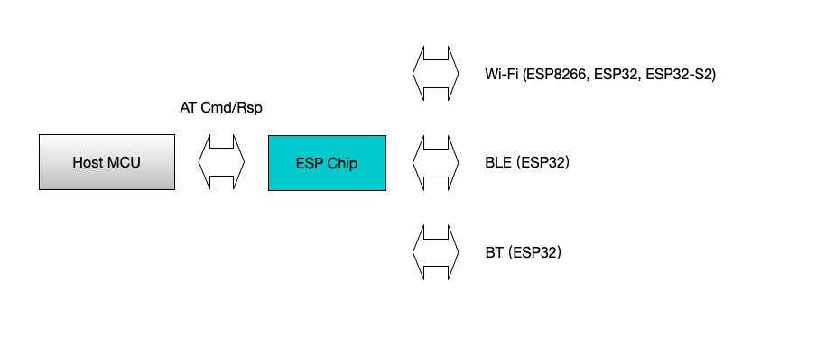
ESP-AT is a project based on ESP-IDF or ESP8266_RTOS_SDK. It makes an ESP
board work as a slave, and an MCU as a host. The host MCU sends AT commands
to the ESP chip and receives AT responses back. ESP-AT provides a wide range
of AT commands with different functions, such as Wi-Fi commands, TCP/IP
commands, Bluetooth LE commands, Bluetooth commands, MQTT commands, HTTP
commands, and Ethernet commands.
Please note that ESP32 AT uses two UART ports: UART0 is used to download
firmware and log output; UART1 is used to send AT commands and receive AT
responses.
All ESP32 modules use GPIO1 and GPIO3 as UART0, but they use different GPIOs
as UART1. The following sections illustrate which GPIOs you should connect for
each ESP32 series of modules.

In my case:
XIAO TX connect to GPIO16 (RX)
XIAO RX connect to GPIO17 (TX)
Wthout hardware flow control., just ignore CTS/RTS.
Suggested to provide separated power supply to ESP32:
At beginning, I power the ESP32-S module from XIAO 3V3. But it re-boot repeatedly, caused by:
Brownout detector was triggered
It's caused by power low. With separated power from breadoard power supply to ESP32-S, this problem fixed.
Nice Blog. Very informative. Thanks for sharing with us. Keep sharing!!
ReplyDeleteBuy Embedded Mini PCs Online