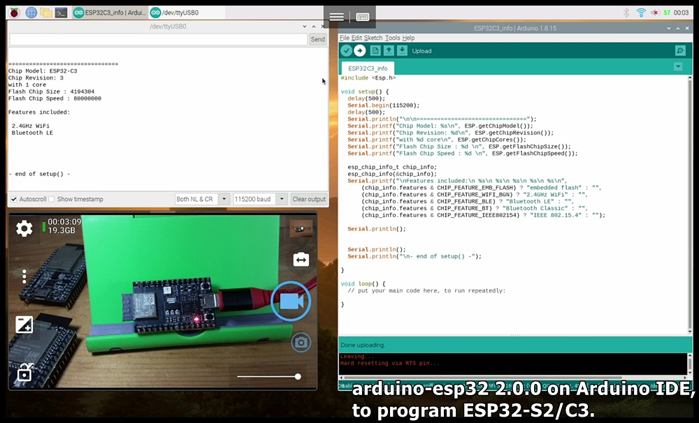
With
arduino-esp32 2.0.0 installed on Arduino IDE, this post run examples on ESP32-DevKitC
V4/ESP32-S2-Saola-1/ESP32-C3-DevKitM-1 to drive SSD1306 I2C OLED, using esp8266-oled-ssd1306 library.
Open Library Manager in Arduino IDE, install "ESP8266 and ESP32 OLED driver
for SSD1306 displays" by ThingPulse, currently 4.2.1. (esp8266-oled-ssd1306)
In the library examples, OLED display is initialized using pre-defined SDA and
SCL based on your board's pins_arduino.h.
With
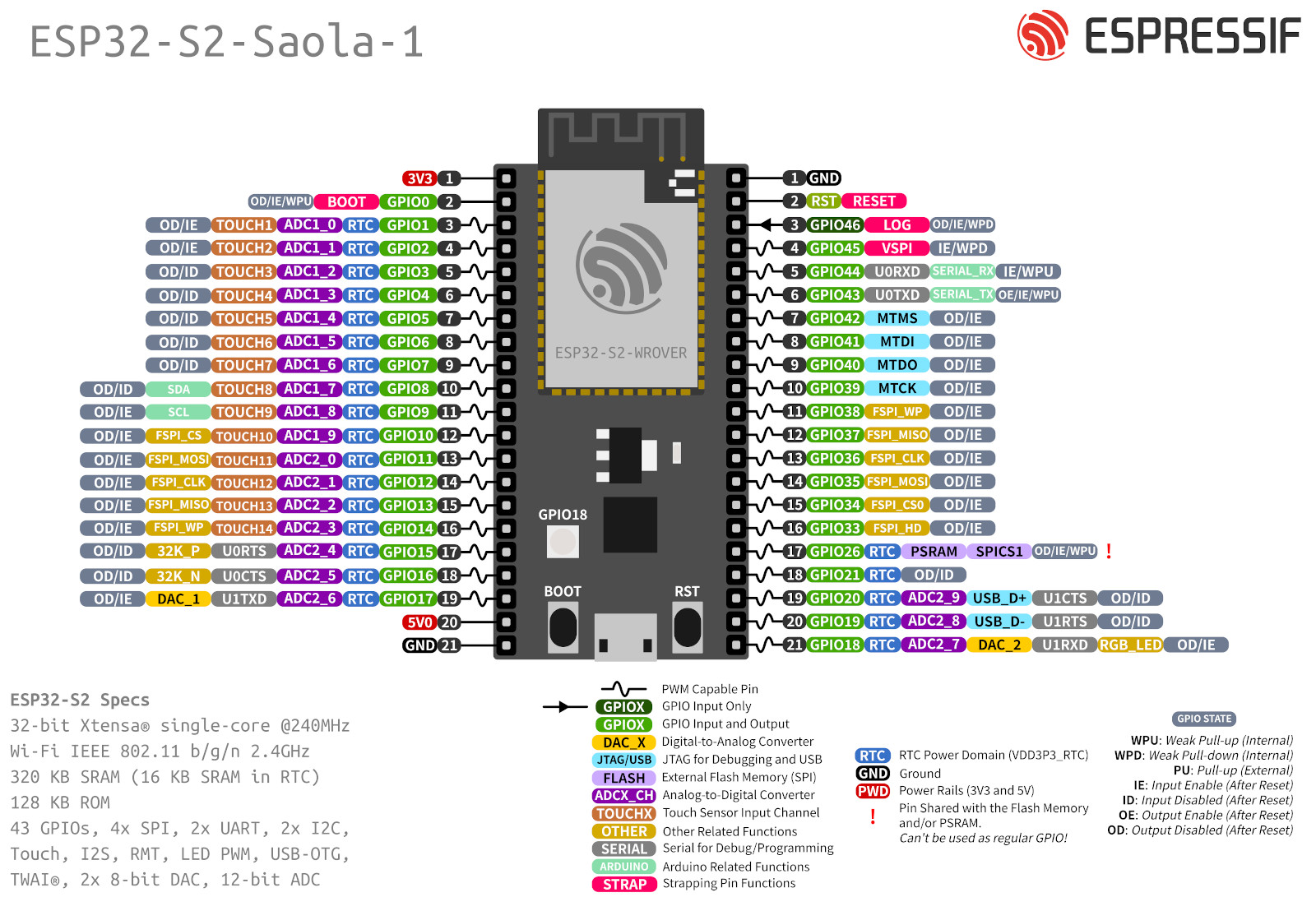
arduino-esp32 2.0.0 installed on Arduino IDE, the following exercise run on ESP32-C3-DevKitM-1/ESP32-S2-Saola-1 to
list the pre-defined function pins of ESP32C3/S2 Dev Module.
This video also show how to locate pins_arduino.h where it defined.
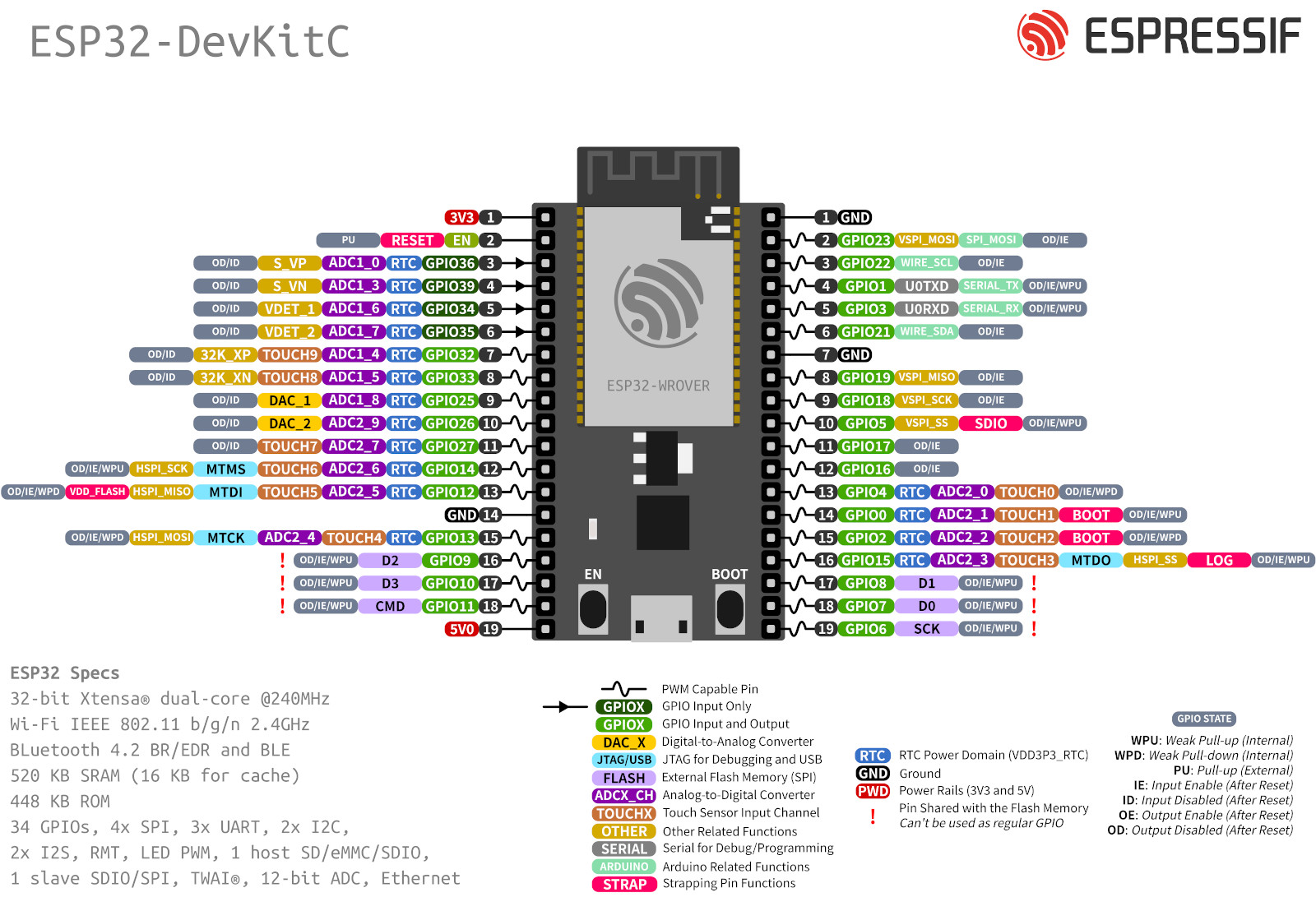
Test on ESP32-C3-DevKitM-1, ESP32-S2-Saola-1 and ESP32-DevKitC
V4.
ESP32C3_pins.ino for board of ESP32C3 Dev Module, run on
ESP32-C3-DevKitM-1
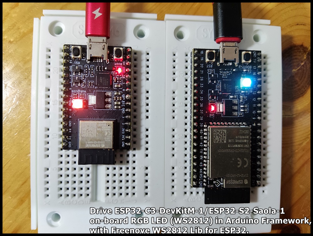
"Freenove WS2812 Lib for ESP32" is an Arduino library for WS2812 led on ESP32. To use this library, open
the Library Manager in the Arduino IDE and install it from there.
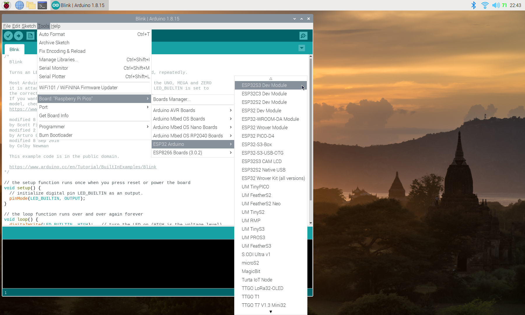
It is aimed to flash MicroPython firmware on ESP32-C3-DevKitM-1
with unknown ESP32-C3 (revision 3) and 4MB flash. I can't find any official
installation instruction, it's found out by my guessing and trying. Not
sure is it correct approach, it seem work for me anyway.
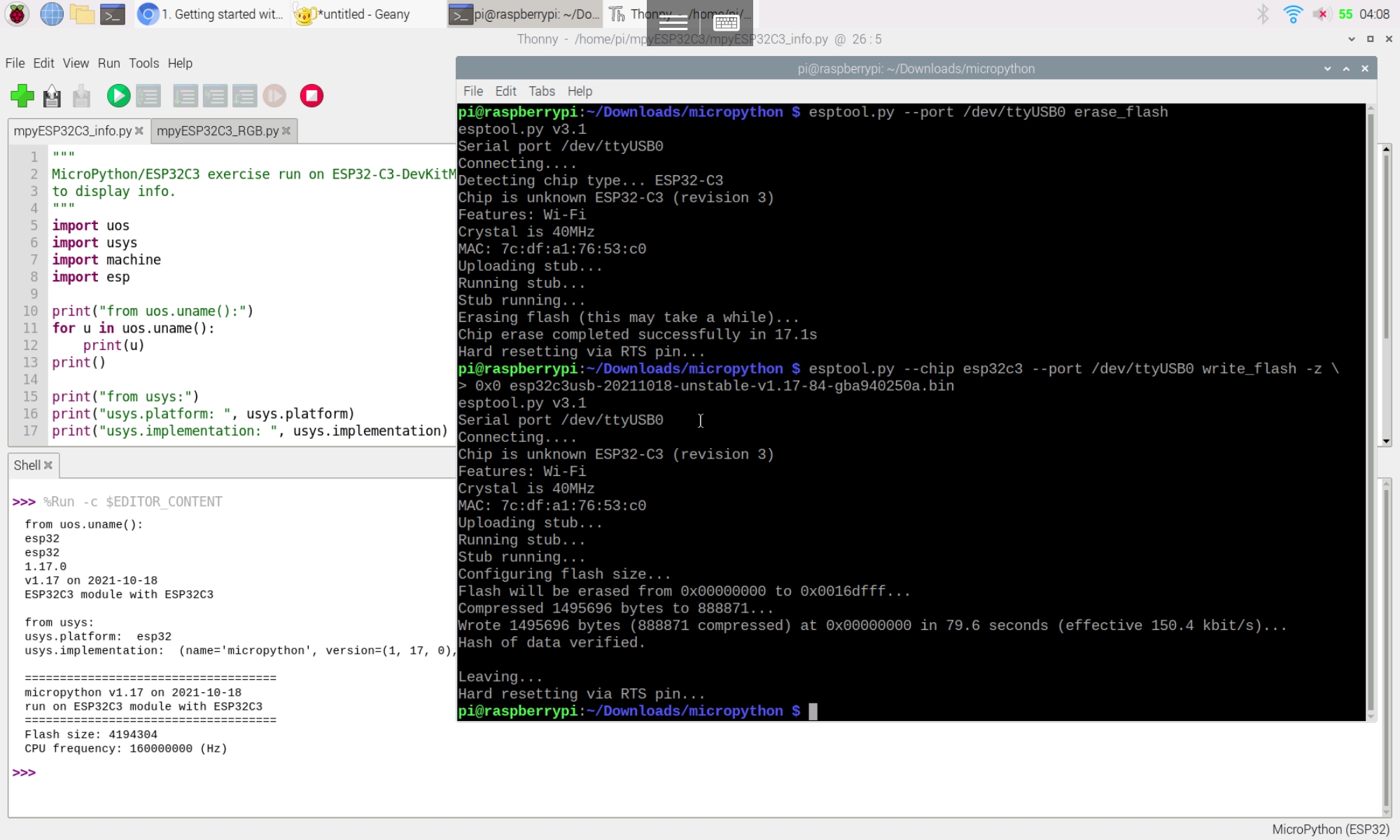
Download MicroPython for ESP32-C3:
Visit https://micropython.org/download/all/, search "esp32c3" firmware for ESP32-C3, download the .bin file.
It's esp32c3usb-20211018-unstable-v1.17-84-gba940250a.bin I tried.
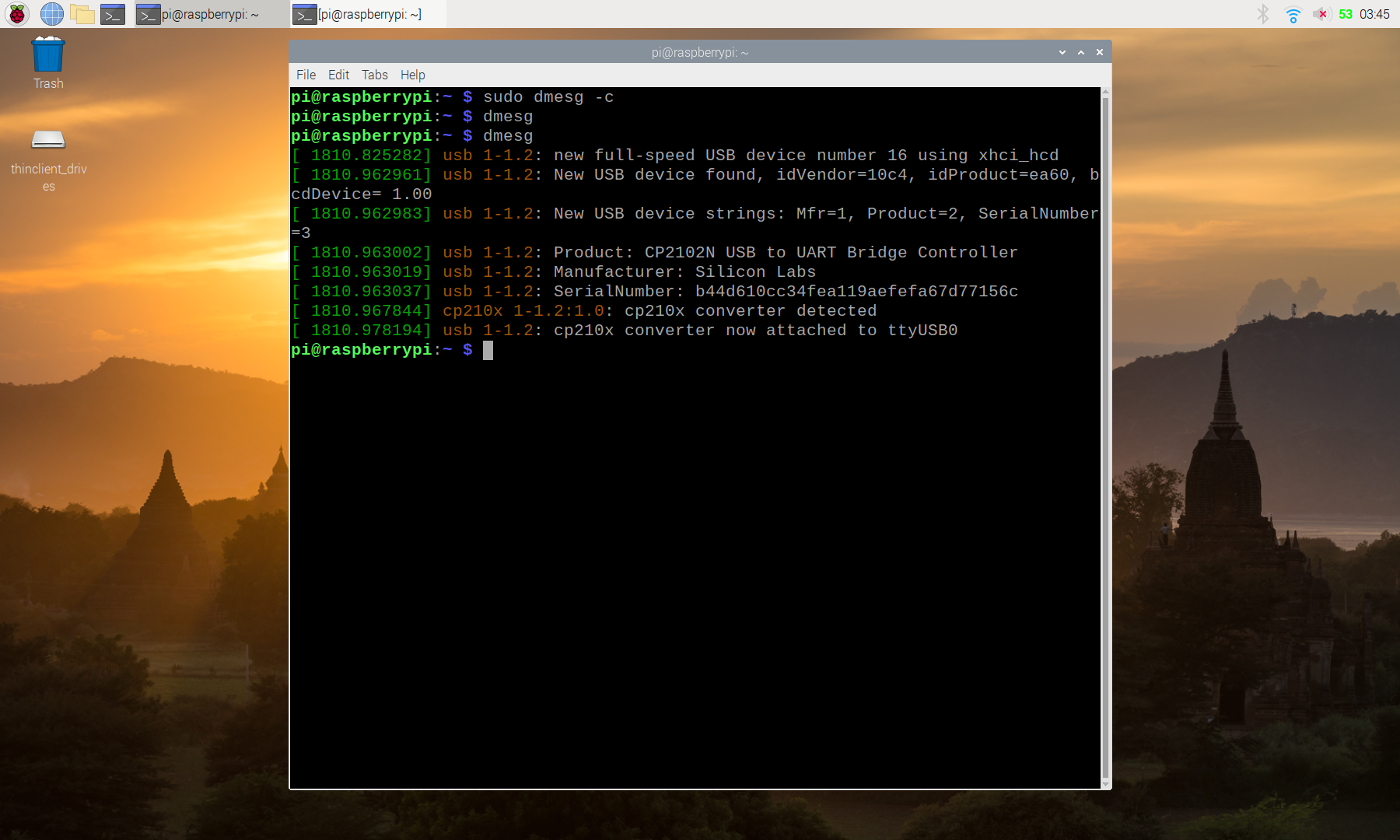
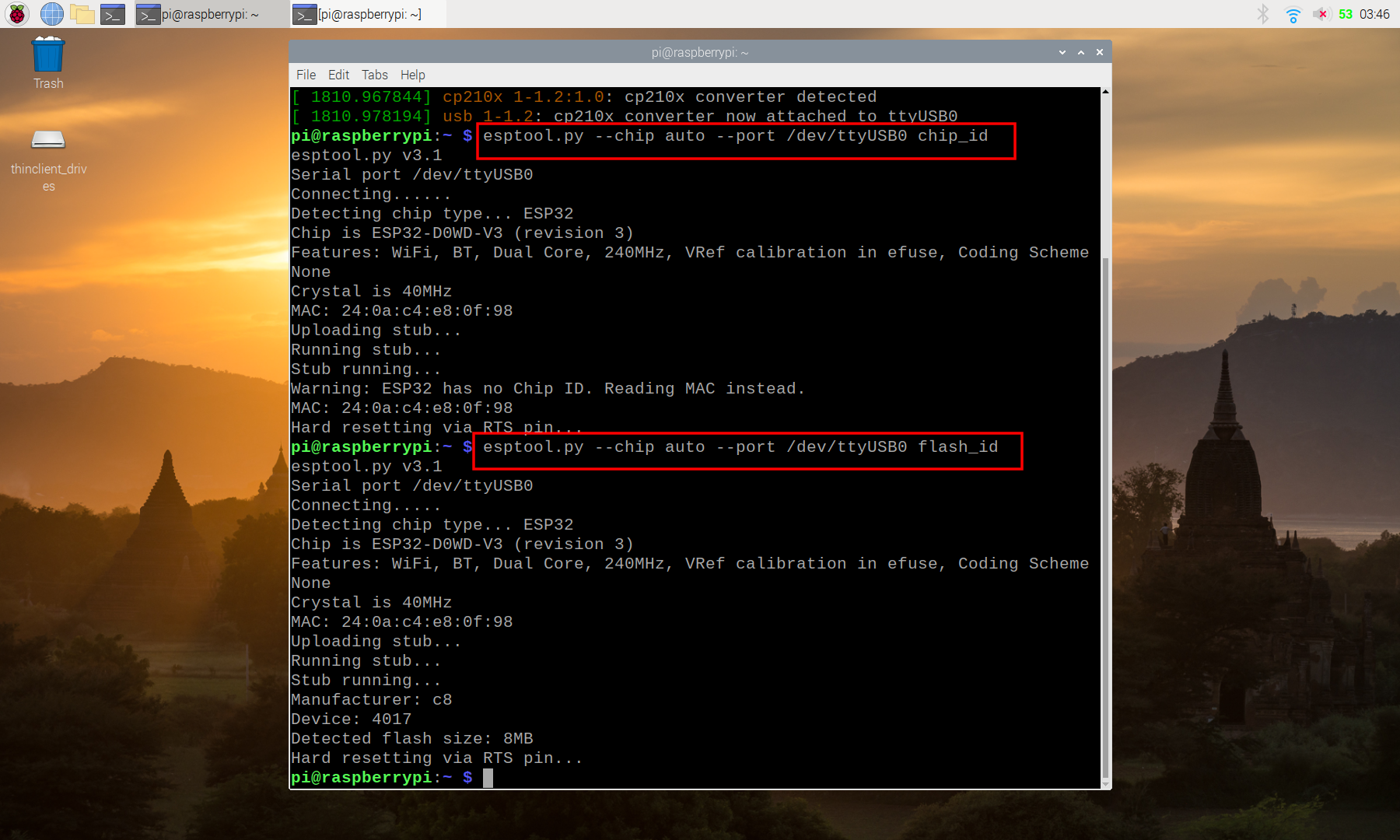
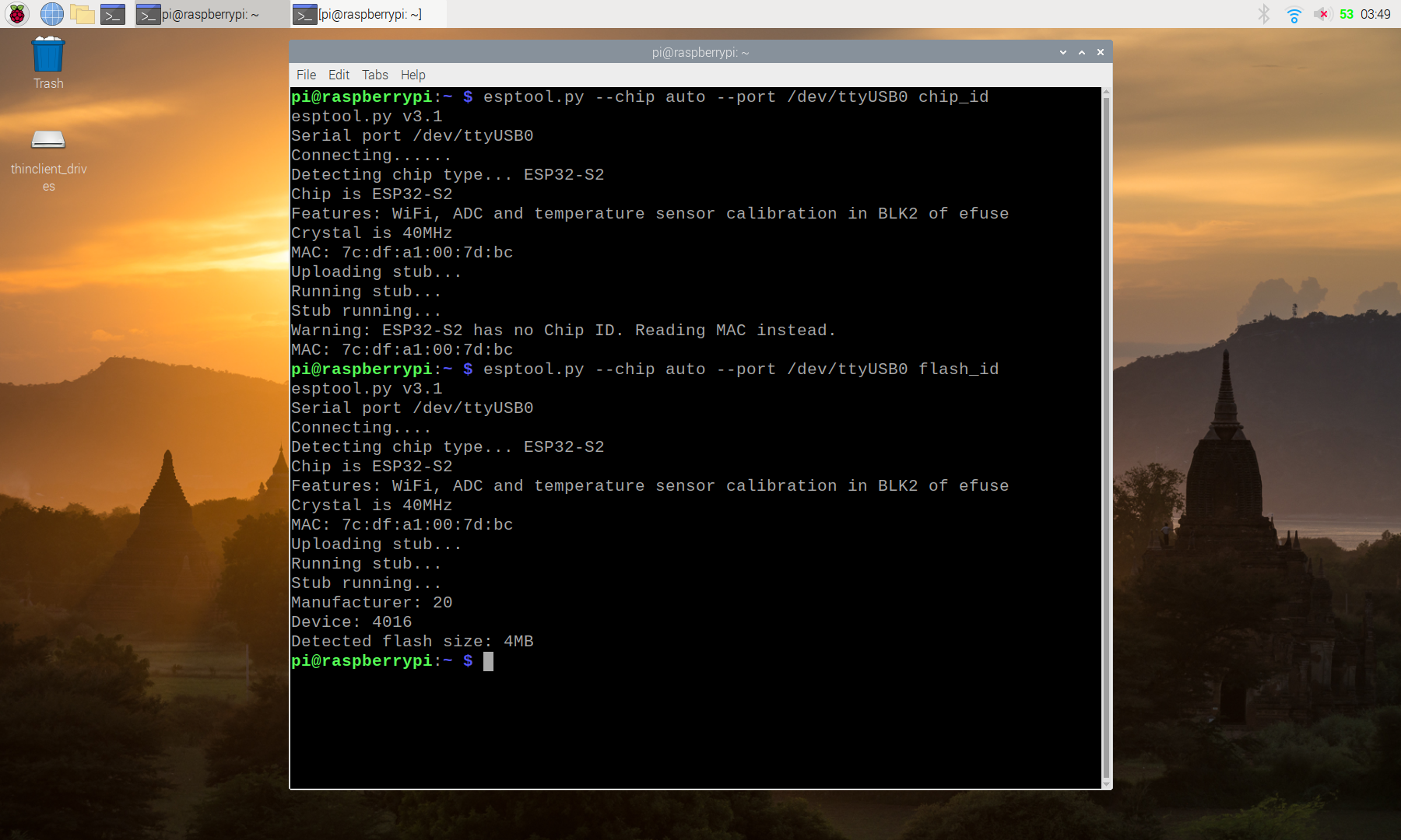
Identify port and chip/flash:
To identify the ESP32 device connected USB port, chip and flash, refer to
the last post.
It's unknown ESP32-C3 (revision 3) and 4MB flash
on ESP32-C3-DevKitM-1, connected to /dev/ttyUSB0.
"""
MicroPython/ESP32C3 exercise run on ESP32-C3-DevKitM-1,
to display info.
"""
import uos
import usys
import machine
import esp

print("from uos.uname():")
for u in uos.uname():
    print(u)
print()

print("from usys:")
print("usys.platform: ", usys.platform)
print("usys.implementation: ", usys.implementation)
print()

print("====================================")
print(usys.implementation[0], uos.uname()[3],
      "\nrun on", uos.uname()[4])
print("====================================")
print("Flash size:", esp.flash_size())
print("CPU frequency:", machine.freq(), "(Hz)")
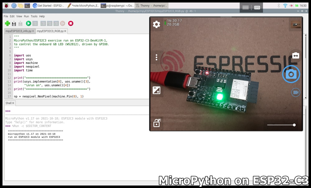
mpyESP32C3_RGB.py
"""
MicroPython/ESP32C3 exercise run on ESP32-C3-DevKitM-1,
to control the onboard GB LED (WS2812), driven by GPIO8.
"""

import uos
import usys
import machine
import neopixel
import time

print("====================================")
print(usys.implementation[0], uos.uname()[3],
      "\nrun on", uos.uname()[4])
print("====================================")

np = neopixel.NeoPixel(machine.Pin(8), 1)

np[0] = (0, 0, 0)
np.write()
time.sleep(1)
np[0] = (100, 100, 100)
np.write()
time.sleep(1)
np[0] = (0, 0, 0)
np.write()
time.sleep(1)

for i in range(256):
    np[0] = (i, 0, 0)
    np.write()
    time.sleep_ms(10)
for i in range(256):
    np[0] = (0, i, 0)
    np.write()
    time.sleep_ms(10)
for i in range(256):
    np[0] = (0, 0, i)
    np.write()
    time.sleep_ms(10)

for i in range(256):
    np[0] = (255-i, 255-i, 255-i)
    np.write()
    time.sleep_ms(10)
To use ST7789 SPI LCD on STM32F411/CircuitPython 7.0.0, basically same as
shown in the post: "CircuitPython 7 exercises on STM32F411, with SPI ST7735 LCD", except using library of adafruit_st7789 instead of using
adafruit_st7735/adafruit_st7735r.
cpyF411_st7789_240x320.py
"""
CircuitPython 7 exercise run on STM32F411
with 2" 240x320 SPI ST7789 IPS

"""

from sys import implementation as sysImplementation
import time
import board
import busio
import displayio
import terminalio

from adafruit_st7789 import ST7789 as TFT_ST77xx
from adafruit_st7789 import __name__ as ST77xx_NAME
from adafruit_st7789 import __version__ as ST77xx_VERSION

from adafruit_display_text import label

# Release any resources currently in use for the displays
displayio.release_displays()

#Connection between STM32F411 and SPI ST7789 display
#marking on display
tft_sck = board.B13     #SCL
tft_mosi = board.A1     #SDA


tft_dc = board.A2       #DC
tft_reset = board.A3    #RES
tft_cs = board.A4       #CS
#Backlight (LED/BLK) connect to STM32F411 3V3
#TFT VCC - STM32F411 3V3
#TFT GND - STM32F411 GND

tft_spi = busio.SPI(clock=tft_sck, MOSI=tft_mosi)
display_bus = displayio.FourWire(
    tft_spi, command=tft_dc, chip_select=tft_cs, reset=tft_reset
)

# I find out colrstart/rowstart by try/error and retry
display = TFT_ST77xx(display_bus, width=320, height=240,
                     colstart=0, rowstart=0,
                     rotation=90,
                     )

print(type(display))
print("display.width:  ", display.width)
print("display.height: ", display.height)

# Make the display context
splash = displayio.Group()
display.show(splash)

color_bitmap = displayio.Bitmap(display.width, display.height, 1)
color_palette = displayio.Palette(1)
color_palette[0] = 0x000000
time.sleep(1)

bg_sprite = displayio.TileGrid(color_bitmap,
                               pixel_shader=color_palette, x=0, y=0)
splash.append(bg_sprite)

for c in [["RED", 0xFF0000],
          ["GREEN", 0x00FF00],
          ["BLUE", 0x0000FF]]:
    print(c[0], " : ", hex(c[1]))
    color_palette[0] = c[1]
    time.sleep(2)

splash.remove(bg_sprite)
#---

# Make the display context
#splash = displayio.Group()
#display.show(splash)

color_bitmap = displayio.Bitmap(display.width, display.height, 1)
color_palette = displayio.Palette(1)
color_palette[0] = 0x00FF00

bg_sprite = displayio.TileGrid(color_bitmap,
                               pixel_shader=color_palette, x=0, y=0)
splash.append(bg_sprite)

# Draw a smaller inner rectangle
inner_bitmap = displayio.Bitmap(display.width-2, display.height-2, 1)
inner_palette = displayio.Palette(1)
inner_palette[0] = 0x0000FF
inner_sprite = displayio.TileGrid(inner_bitmap,
                                  pixel_shader=inner_palette, x=1, y=1)
splash.append(inner_sprite)

# Draw a label
text_group1 = displayio.Group(scale=1, x=5, y=10)
text1 = "STM32F411"
text_area1 = label.Label(terminalio.FONT, text=text1, color=0xFF0000)
text_group1.append(text_area1)  # Subgroup for text scaling

# Draw a label
strSys = sysImplementation[0] + ' ' + \
         str(sysImplementation[1][0]) +'.'+ \
         str(sysImplementation[1][1]) +'.'+ \
         str(sysImplementation[1][2])
text_group2 = displayio.Group(scale=1, x=5, y=25)
text2 = strSys
text_area2 = label.Label(terminalio.FONT, text=text2, color=0xFFFFFF)
text_group2.append(text_area2)  # Subgroup for text scaling

# Draw a label
text_group3 = displayio.Group(scale=1, x=5, y=40)
text3 = ST77xx_NAME
text_area3 = label.Label(terminalio.FONT, text=text3, color=0x0000000)
text_group3.append(text_area3)  # Subgroup for text scaling
# Draw a label
text_group4 = displayio.Group(scale=1, x=5, y=55)
text4 = ST77xx_VERSION
text_area4 = label.Label(terminalio.FONT, text=text4, color=0x000000)
text_group4.append(text_area4)  # Subgroup for text scaling

text_group5 = displayio.Group(scale=1, x=5, y=70)
text5 = str(display.width) + " x " + str(display.height)
text_area5 = label.Label(terminalio.FONT, text=text5, color=0x000000)
text_group5.append(text_area5)  # Subgroup for text scaling

splash.append(text_group1)
splash.append(text_group2)
splash.append(text_group3)
splash.append(text_group4)
splash.append(text_group5)

time.sleep(3.0)

rot = 90
while True:
    time.sleep(5.0)
    rot = rot + 90
    if (rot>=360):
        rot =0
    display.rotation = rot
The former STM32F411/CircuitPython 7 exercise show
display on SPI ST7735 LCD. This exercise connect to a MicroSD card adapter, read text file, load
bitmap and display on SPI ST7735 LCD.
The MicroSD adapter used support Micro SD <=2G, Micro SDHC <=32G,
require operating voltage of 4.5~5.5V, with 3.3/5V interface voltage. So
connect STM32F411 5V to MicroSD adapter's VCC, GND to GND. Other pins refer to
the exercise code, marked in blue.
The libraries needed in this exercise include adafruit_sdcard.mpy,
adafruit_st7735r.mpy and adafruit_imageload.
Visit https://circuitpython.org/libraries, download the appropriate bundle
(adafruit-circuitpython-bundle-7.x-mpy- here) for your version of
CircuitPython. Unzip the file, copy adafruit_sdcard.mpy, adafruit_st7735r.mpy
and adafruit_imageload folder from the "lib" folder to the "lib" folder on
your CIRCUITPY drive. (refer to the video in last post "CircuitPython 7 exercises on STM32F411, with SSD1306 I2C OLED")
Exercise code
cpyF411_SD.py, simple print the files in microSD. There are one text file (hello.txt) and three bmp files (logo.bmp, photo_01.bmp and photo_02.bmp) in my microSD card.
cpyF411_SD_textfile.py, read the "hello.txt" from microSD Card.
"""
CircuitPython exercise running on STM32F411:
Read SD Card using adafruit_sdcard library

Read the "hello.txt" from SD Card
"""

import board
from sys import implementation as sysImplementation
import busio
import digitalio
import adafruit_sdcard
import storage
import os

sd_path = "/sd"

print(board.board_id)
strSys = sysImplementation[0] + ' ' + \
         str(sysImplementation[1][0]) +'.'+ \
         str(sysImplementation[1][1]) +'.'+ \
         str(sysImplementation[1][2])
print(strSys)
print(adafruit_sdcard.__name__, " ", adafruit_sdcard.__version__)
print()

#Connection between SDCard and STM32F411
#SD Card VCC - 5V
#SD Card GND - GND
sd_SCK = board.B3
sd_MISO = board.B4
sd_MOSI = board.B5
sd_CS = board.A15
spi = busio.SPI(sd_SCK, sd_MOSI, sd_MISO)
cs = digitalio.DigitalInOut(sd_CS)

# ref:
# https://circuitpython.readthedocs.io/projects/sd/en/3.3.5/examples.html
def print_directory(path, tabs=0):
    for file in os.listdir(path):
        stats = os.stat(path + "/" + file)
        filesize = stats[6]
        isdir = stats[0] & 0x4000

        if filesize < 1000:
            sizestr = str(filesize) + " by"
        elif filesize < 1000000:
            sizestr = "%0.1f KB" % (filesize / 1000)
        else:
            sizestr = "%0.1f MB" % (filesize / 1000000)

        prettyprintname = ""
        for _ in range(tabs):
            prettyprintname += "   "
        prettyprintname += file
        if isdir:
            prettyprintname += "/"
        print('{0:<40} Size: {1:>10}'.format(prettyprintname, sizestr))

        # recursively print directory contents
        if isdir:
            print_directory(path + "/" + file, tabs + 1)

try:
    sdcard = adafruit_sdcard.SDCard(spi, cs)
    vfs = storage.VfsFat(sdcard)
    storage.mount(vfs, sd_path)

    print("Files on filesystem:")
    print("====================")
    print_directory(sd_path)
    print("====================")
    print()

    textfile = sd_path+"/hello.txt"
    print("text file:", textfile)
    print("========================")
    with open(textfile, "r") as f:
        line = f.readline()
        while line != '':
            print(line)
            line = f.readline()


except OSError as exc:
    print(exc.args[0])
cpyF411_SD_bitmap_logo.py, read a single bmp file (logo.bmp) from SD Card using displayio.OnDiskBitmap(), and display on SPI ST7735 LCD
"""
CircuitPython exercise running on STM32F411:
Read SD Card using adafruit_sdcard library

Read a single bmp from SD Card using displayio.OnDiskBitmap()

and display on SPI ST7735 LCD
"""

import board
from sys import implementation as sysImplementation
import busio
import digitalio
import adafruit_sdcard
import storage
import os
import displayio

from adafruit_st7735r import ST7735R as TFT_ST7735
from adafruit_st7735r import __name__ as ST7735_NAME
from adafruit_st7735r import __version__ as ST7735_VERSION

# Release any resources currently in use for the displays
displayio.release_displays()

sd_path = "/sd"

print(board.board_id)
strSys = sysImplementation[0] + ' ' + \
         str(sysImplementation[1][0]) +'.'+ \
         str(sysImplementation[1][1]) +'.'+ \
         str(sysImplementation[1][2])
print(strSys)
print(adafruit_sdcard.__name__, " ", adafruit_sdcard.__version__)
print(ST7735_NAME, " ", ST7735_VERSION)
print()

#Connection between SDCard and STM32F411
#SD Card VCC - 5V
#SD Card GND - GND
sd_SCK = board.B3
sd_MISO = board.B4
sd_MOSI = board.B5
sd_CS = board.A15
sd_spi = busio.SPI(sd_SCK, sd_MOSI, sd_MISO)
sd_cs = digitalio.DigitalInOut(sd_CS)

#Connection between STM32F411 and SPI ST7735 display
#marking on display     #128x128   #80x160
tft_sck = board.B13     #SCK       #SCL
tft_mosi = board.A1     #SDA       #SDA

tft_dc = board.A2       #A0        #DC
tft_reset = board.A3    #RESET     #RES
tft_cs = board.A4       #CS        #CS
#Backlight (LED/BLK) connect to STM32F411 3V3
#TFT VCC - STM32F411 3V3
#TFT GND - STM32F411 GND

tft_spi = busio.SPI(clock=tft_sck, MOSI=tft_mosi)
display_bus = displayio.FourWire(
    tft_spi, command=tft_dc, chip_select=tft_cs, reset=tft_reset
)

# I find out colrstart/rowstart by try/error and retry
display = TFT_ST7735(display_bus, width=128, height=128,
                     rotation=180,
                     bgr=True)

print(type(display))
print("display.width:  ", display.width)
print("display.height: ", display.height)
print()

try:
    sdcard = adafruit_sdcard.SDCard(sd_spi, sd_cs)
    vfs = storage.VfsFat(sdcard)
    storage.mount(vfs, sd_path)

    print("========================")
    bmpfile = sd_path+"/logo.bmp"
    print("bitmap file:", bmpfile)

    bitmap = displayio.OnDiskBitmap(bmpfile)

    # Create a TileGrid to hold the bitmap
    tile_grid = displayio.TileGrid(bitmap, pixel_shader=bitmap.pixel_shader)

    # Create a Group to hold the TileGrid
    group = displayio.Group()

    # Add the TileGrid to the Group
    group.append(tile_grid)

    # Add the Group to the Display
    display.show(group)


except OSError as exc:
    print(exc.args[0])

while True:
    pass
displayio.OnDiskBitmap vs adafruit_imageload
OnDiskBitmap source the bitmap image directly from flash memory storage. This is like reading the image from disk instead of loading it into memory first imageload). The trade off of using OnDiskBitmap is the reduced use of memory for potentially slower pixel draw times.
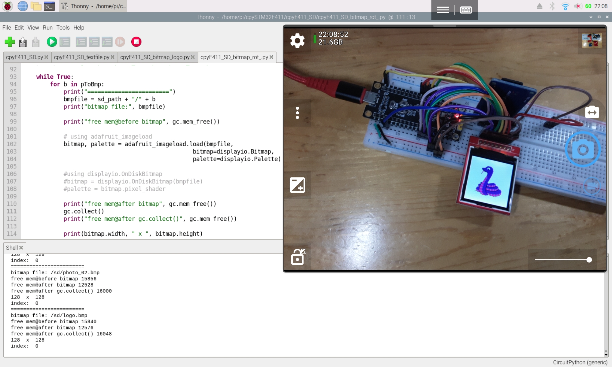
cpyF411_SD_bitmap_rot_.py, repeatedly load bmp files (logo.bmp, photo_01.bmp and photo_02.bmp) from SD Card using adafruit_imageload (marked in red) or displayio.OnDiskBitmap (marked in green), then display on SPI ST7735 LCD.
"""
CircuitPython exercise running on STM32F411:
Read SD Card using adafruit_sdcard library
Repeatly load bmp(s) from SD Card using:
- adafruit_imageload
- displayio.OnDiskBitmap
and display on SPI ST7735 LCD
"""
import board
from sys import implementation as sysImplementation
import busio
import digitalio
import adafruit_sdcard
import storage
import os
import displayio
import adafruit_imageload
import time
from adafruit_st7735r import ST7735R as TFT_ST7735
from adafruit_st7735r import __name__ as ST7735_NAME
from adafruit_st7735r import __version__ as ST7735_VERSION
import gc
# Release any resources currently in use for the displays
displayio.release_displays()
gc.collect()
sd_path = "/sd"
print(board.board_id)
strSys = sysImplementation[0] + ' ' + \
str(sysImplementation[1][0]) +'.'+ \
str(sysImplementation[1][1]) +'.'+ \
str(sysImplementation[1][2])
print(strSys)
print(adafruit_sdcard.__name__, " ", adafruit_sdcard.__version__)
print(adafruit_imageload.__name__, " ", adafruit_imageload.__version__)
print(ST7735_NAME, " ", ST7735_VERSION)
print()
#Connection between SDCard and STM32F411
#SD Card VCC - 5V
#SD Card GND - GND
sd_SCK = board.B3
sd_MISO = board.B4
sd_MOSI = board.B5
sd_CS = board.A15
sd_spi = busio.SPI(sd_SCK, sd_MOSI, sd_MISO)
sd_cs = digitalio.DigitalInOut(sd_CS)
#Connection between STM32F411 and SPI ST7735 display
#marking on display #128x128 #80x160
tft_sck = board.B13 #SCK #SCL
tft_mosi = board.A1 #SDA #SDA
tft_dc = board.A2 #A0 #DC
tft_reset = board.A3 #RESET #RES
tft_cs = board.A4 #CS #CS
#Backlight (LED/BLK) connect to STM32F411 3V3
#TFT VCC - STM32F411 3V3
#TFT GND - STM32F411 GND
tft_spi = busio.SPI(clock=tft_sck, MOSI=tft_mosi)
display_bus = displayio.FourWire(
tft_spi, command=tft_dc, chip_select=tft_cs, reset=tft_reset
)
# I find out colrstart/rowstart by try/error and retry
display = TFT_ST7735(display_bus, width=128, height=128,
rotation=180,
bgr=True)
print(type(display))
print("display.width: ", display.width)
print("display.height: ", display.height)
print()
try:
sdcard = adafruit_sdcard.SDCard(sd_spi, sd_cs)
vfs = storage.VfsFat(sdcard)
storage.mount(vfs, sd_path)
# Create a Group to hold the TileGrid
group = displayio.Group()
pToBmp = ["logo.bmp", "photo_01.bmp", "photo_02.bmp"]
while True:
for b in pToBmp:
print("========================")
bmpfile = sd_path + "/" + b
print("bitmap file:", bmpfile)
print("free mem@before bitmap", gc.mem_free())
# using adafruit_imageload
bitmap, palette = adafruit_imageload.load(bmpfile,
bitmap=displayio.Bitmap,
palette=displayio.Palette)#using displayio.OnDiskBitmap
#bitmap = displayio.OnDiskBitmap(bmpfile)
#palette = bitmap.pixel_shader
print("free mem@after bitmap", gc.mem_free())
gc.collect()
print("free mem@after gc.collect()", gc.mem_free())
print(bitmap.width, " x ", bitmap.height)
# Create a TileGrid to hold the bitmap
tile_grid = displayio.TileGrid(bitmap, pixel_shader=palette)
# Add the TileGrid to the Group
group.append(tile_grid)
print("index: ", group.index(tile_grid))
# Add the Group to the Display
display.show(group)
time.sleep(3)
group.remove(tile_grid)
except OSError as exc:
print(exc.args[0])
while True:
pass
bmp files used here:
logo.bmp
photo_01.bmp
photo_02.bmp
Not all BMP file formats are supported by CircuitPython. You will need to make sure you have an indexed BMP file. Follow HERE for some good info on how to convert or create such a BMP file.
Many pins on CircuitPython compatible microcontroller boards have multiple
names, however, typically, there's only one name labeled on the physical
board. So how do you find out what the other available pin names are? Simple,
with the following script! Each line printed out to the serial console
contains the set of names for a particular pin.
"""CircuitPython Essentials Pin Map Script"""
import microcontroller
import board

board_pins = []
for pin in dir(microcontroller.pin):
    if isinstance(getattr(microcontroller.pin, pin), microcontroller.Pin):
        pins = []
        for alias in dir(board):
            if getattr(board, alias) is getattr(microcontroller.pin, pin):
                pins.append("board.{}".format(alias))
        if len(pins) > 0:
            board_pins.append(" ".join(pins))
for pins in sorted(board_pins):
    print(pins)
Tested on STM32F411 Dev. Board with CircuitPython 7.0.0
List I2C possible pin-pair
"""CircuitPython Essentials I2C possible pin-pair identifying script"""
import board
import busio
from microcontroller import Pin

def is_hardware_I2C(scl, sda):
    try:
        p = busio.I2C(scl, sda)
        p.deinit()
        return True
    except ValueError:
        return False
    except RuntimeError:
        return True

def get_unique_pins():
    exclude = ['NEOPIXEL', 'APA102_MOSI', 'APA102_SCK']
    pins = [pin for pin in [
        getattr(board, p) for p in dir(board) if p not in exclude]
            if isinstance(pin, Pin)]
    unique = []
    for p in pins:
        if p not in unique:
            unique.append(p)
    return unique

for scl_pin in get_unique_pins():
    for sda_pin in get_unique_pins():
        if scl_pin is sda_pin:
            continue
        if is_hardware_I2C(scl_pin, sda_pin):
            print("SCL pin:", scl_pin, "\t SDA pin:", sda_pin)
adafruit_st7735, adafruit_st7735r and adafruit_display_text are needed in the
following exercises.
Visit
https://circuitpython.org/libraries, download the appropriate bundle (adafruit-circuitpython-bundle-7.x-mpy-
here) for your version of CircuitPython. Unzip the file, copy
adafruit_st7735.mpy, adafruit_st7735r.mpy and adafruit_display_text folder
from the "lib" folder to the "lib" folder on your CIRCUITPY drive. (refer to
the video in last post "CircuitPython 7 exercises on STM32F411, with SSD1306 I2C OLED")
Connection
Please notice that 1.44" 128x128 (KMR1441_SPI V2) and 1.8" 128x160 TFT have
same pin assignment, 0.96" 80x160 IPS have different pin order and pin name
but same function.
The connection refer to the exercise code, marked
blue.
Exercise code
The code in red show the difference between
them.
cpyF411_st7735_128x128.py for 1.44" 128x128 (KMR1441_SPI V2)
"""
CircuitPython 7 exercise run on STM32F411
with 128x128 SPI ST7735

ref:
adafruit/Adafruit_CircuitPython_ST7735
https://github.com/adafruit/Adafruit_CircuitPython_ST7735
adafruit/Adafruit_CircuitPython_ST7735R
https://github.com/adafruit/Adafruit_CircuitPython_ST7735R
"""

from sys import implementation as sysImplementation
import time
import board
import busio
import displayio
import terminalio

from adafruit_st7735 import ST7735 as TFT_ST7735
from adafruit_st7735 import __name__ as ST7735_NAME
from adafruit_st7735 import __version__ as ST7735_VERSION

from adafruit_display_text import label

# Release any resources currently in use for the displays
displayio.release_displays()

#Connection between STM32F411 and SPI ST7735 display
#marking on display     #128x128   #80x160
tft_sck = board.B13     #SCK       #SCL
tft_mosi = board.A1     #SDA       #SDA

tft_dc = board.A2       #A0        #DC
tft_reset = board.A3    #RESET     #RES
tft_cs = board.A4       #CS        #CS
#Backlight (LED/BLK) connect to STM32F411 3V3
#TFT VCC - STM32F411 3V3
#TFT GND - STM32F411 GND

tft_spi = busio.SPI(clock=tft_sck, MOSI=tft_mosi)
display_bus = displayio.FourWire(
    tft_spi, command=tft_dc, chip_select=tft_cs, reset=tft_reset
)

# I find out colrstart/rowstart by try/error and retry
display = TFT_ST7735(display_bus, width=128, height=128,
                     rotation=90,
                     )

print(type(display))
print("display.width:  ", display.width)
print("display.height: ", display.height)

# Make the display context
splash = displayio.Group()
display.show(splash)

color_bitmap = displayio.Bitmap(display.width, display.height, 1)
color_palette = displayio.Palette(1)
color_palette[0] = 0x000000
time.sleep(1)

bg_sprite = displayio.TileGrid(color_bitmap,
                               pixel_shader=color_palette, x=0, y=0)
splash.append(bg_sprite)

for c in [["RED", 0xFF0000],
          ["GREEN", 0x00FF00],
          ["BLUE", 0x0000FF]]:
    print(c[0], " : ", hex(c[1]))
    color_palette[0] = c[1]
    time.sleep(2)

splash.remove(bg_sprite)
#---

# Make the display context
#splash = displayio.Group()
#display.show(splash)

color_bitmap = displayio.Bitmap(display.width, display.height, 1)
color_palette = displayio.Palette(1)
color_palette[0] = 0x00FF00

bg_sprite = displayio.TileGrid(color_bitmap,
                               pixel_shader=color_palette, x=0, y=0)
splash.append(bg_sprite)

# Draw a smaller inner rectangle
inner_bitmap = displayio.Bitmap(display.width-2, display.height-2, 1)
inner_palette = displayio.Palette(1)
inner_palette[0] = 0x0000FF
inner_sprite = displayio.TileGrid(inner_bitmap,
                                  pixel_shader=inner_palette, x=1, y=1)
splash.append(inner_sprite)

# Draw a label
text_group1 = displayio.Group(scale=1, x=5, y=10)
text1 = "STM32F411"
text_area1 = label.Label(terminalio.FONT, text=text1, color=0xFF0000)
text_group1.append(text_area1)  # Subgroup for text scaling

# Draw a label
strSys = sysImplementation[0] + ' ' + \
         str(sysImplementation[1][0]) +'.'+ \
         str(sysImplementation[1][1]) +'.'+ \
         str(sysImplementation[1][2])
text_group2 = displayio.Group(scale=1, x=5, y=25)
text2 = strSys
text_area2 = label.Label(terminalio.FONT, text=text2, color=0xFFFFFF)
text_group2.append(text_area2)  # Subgroup for text scaling

# Draw a label
text_group3 = displayio.Group(scale=1, x=5, y=40)
text3 = ST7735_NAME
text_area3 = label.Label(terminalio.FONT, text=text3, color=0x0000000)
text_group3.append(text_area3)  # Subgroup for text scaling
# Draw a label
text_group4 = displayio.Group(scale=1, x=5, y=55)
text4 = ST7735_VERSION
text_area4 = label.Label(terminalio.FONT, text=text4, color=0x000000)
text_group4.append(text_area4)  # Subgroup for text scaling

text_group5 = displayio.Group(scale=1, x=5, y=70)
text5 = str(display.width) + " x " + str(display.height)
text_area5 = label.Label(terminalio.FONT, text=text5, color=0x000000)
text_group5.append(text_area5)  # Subgroup for text scaling

splash.append(text_group1)
splash.append(text_group2)
splash.append(text_group3)
splash.append(text_group4)
splash.append(text_group5)

time.sleep(3.0)

rot = 90
while True:
    time.sleep(5.0)
    rot = rot + 90
    if (rot>=360):
        rot =0
    display.rotation = rot
cpyF411_st7735_80x160.py for 0.96" 80x160 IPS
"""
CircuitPython 7 exercise run on STM32F411
with 80x160 SPI ST7735 IPS

ref:
adafruit/Adafruit_CircuitPython_ST7735
https://github.com/adafruit/Adafruit_CircuitPython_ST7735
adafruit/Adafruit_CircuitPython_ST7735R
https://github.com/adafruit/Adafruit_CircuitPython_ST7735R
"""

from sys import implementation as sysImplementation
import time
import board
import busio
import displayio
import terminalio

from adafruit_st7735r import ST7735R as TFT_ST7735
from adafruit_st7735r import __name__ as ST7735_NAME
from adafruit_st7735r import __version__ as ST7735_VERSION

from adafruit_display_text import label

# Release any resources currently in use for the displays
displayio.release_displays()

#Connection between STM32F411 and SPI ST7735 display
#marking on display     #128x128   #80x160
tft_sck = board.B13     #SCK       #SCL
tft_mosi = board.A1     #SDA       #SDA

tft_dc = board.A2       #A0        #DC
tft_reset = board.A3    #RESET     #RES
tft_cs = board.A4       #CS        #CS
#Backlight (LED/BLK) connect to STM32F411 3V3
#TFT VCC - STM32F411 3V3
#TFT GND - STM32F411 GND

tft_spi = busio.SPI(clock=tft_sck, MOSI=tft_mosi)
display_bus = displayio.FourWire(
    tft_spi, command=tft_dc, chip_select=tft_cs, reset=tft_reset
)

# I find out colrstart/rowstart by try/error and retry
display = TFT_ST7735(display_bus, width=160, height=80,
                     colstart=26, rowstart=1,
                     rotation=90,
                     invert=True
                     )

print(type(display))
print("display.width:  ", display.width)
print("display.height: ", display.height)

	[... same as in cpyF411_st7735_128x128.py ...]
cpyF411_st7735_128x160.py for 1.8" 128x160 TFT
"""
CircuitPython 7 exercise run on STM32F411
with 128x160 SPI ST7735

ref:
adafruit/Adafruit_CircuitPython_ST7735
https://github.com/adafruit/Adafruit_CircuitPython_ST7735
adafruit/Adafruit_CircuitPython_ST7735R
https://github.com/adafruit/Adafruit_CircuitPython_ST7735R
"""

from sys import implementation as sysImplementation
import time
import board
import busio
import displayio
import terminalio

from adafruit_st7735r import ST7735R as TFT_ST7735
from adafruit_st7735r import __name__ as ST7735_NAME
from adafruit_st7735r import __version__ as ST7735_VERSION

from adafruit_display_text import label

# Release any resources currently in use for the displays
displayio.release_displays()

#Connection between STM32F411 and SPI ST7735 display
#marking on display     #128x128   #80x160
                        #128x160
tft_sck = board.B13     #SCK       #SCL
tft_mosi = board.A1     #SDA       #SDA

tft_dc = board.A2       #A0        #DC
tft_reset = board.A3    #RESET     #RES
tft_cs = board.A4       #CS        #CS
#Backlight (LED/BLK) connect to STM32F411 3V3
#TFT VCC - STM32F411 3V3
#TFT GND - STM32F411 GND

tft_spi = busio.SPI(clock=tft_sck, MOSI=tft_mosi)
display_bus = displayio.FourWire(
    tft_spi, command=tft_dc, chip_select=tft_cs, reset=tft_reset
)

# I find out colrstart/rowstart by try/error and retry
display = TFT_ST7735(display_bus, width=160, height=128,
                     rotation=90,
                     )

print(type(display))
print("display.width:  ", display.width)
print("display.height: ", display.height)

	[... same as in cpyF411_st7735_128x128.py ...]
To run the exercise code, Adafruit CircuitPython Library Bundle's
adafruit_ssd1306 and font5x8.bin is need.
Visit
https://circuitpython.org/libraries, download the appropriate bundle (adafruit-circuitpython-bundle-7.x-mpy-
here) for your version of CircuitPython.
Unzip the file, copy adafruit_ssd1306.mpy, and
adafruit_framebuf.mpy from the "lib" folder to the lib folder on your CIRCUITPY drive.
And copy font5x8.bin from the unzipped "examples" folder to CIRCUITPY driver.
Exercise code
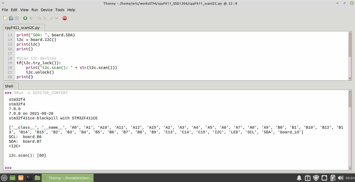
cpyF411_scanI2C.py, scan the address of connected I2C devices.
import os
import busio
import board

for u in os.uname():
    print(u)
print()

#Assign I2C:
#https://circuitpython.readthedocs.io/en/latest/shared-bindings/board/index.html#board.I2C
print(dir(board))
print("SCL: ", board.SCL)
print("SDA: ", board.SDA)
i2c = board.I2C()
print(i2c)
print()

#Scan I2C devices
if(i2c.try_lock()):
    print("i2c.scan(): " + str(i2c.scan()))
    i2c.unlock()
print()
cpyF411_SSD1306.py
from os import uname
from board import SCL, SDA
from sys import implementation as sysImplementation
import busio
import time

import adafruit_ssd1306


# Create the I2C interface and display object of SSD1306_I2C.
i2c = busio.I2C(SCL, SDA)
display = adafruit_ssd1306.SSD1306_I2C(128, 64, i2c)

for u in uname():
    print(u)
print()
for s in sysImplementation:
    print(s)
print()

print(display)
print("display.width x height: ", display.width, " x ", display.height)
print(dir(display))

display.fill(0)
display.show()
time.sleep(1)
display.fill(1)
display.show()
time.sleep(1)

display.fill(0)


strSys = sysImplementation[0] + ' ' + \
         str(sysImplementation[1][0]) +'.'+ \
         str(sysImplementation[1][1]) +'.'+ \
         str(sysImplementation[1][2])

strLib = adafruit_ssd1306.__name__ + '\n' + adafruit_ssd1306.__version__

def drawInfo():
    display.text(strSys, 0, 0, 1)
    display.text(strLib, 0, 10, 1)
    display.text("STM32F411", 0, 30, 1)
    display.text("SSD1306", 0, 40, 1)
    strResolution = str(display.rotation) + ' : ' + str(display.width) + ' x ' + str(display.height)
    display.text(strResolution, 0, 50, 1)

for r in range(0, 4):
    display.fill(0)
    display.rotation = r
    drawInfo()
    display.show()
    time.sleep(3)

display.rotation = 0

#draw rectangle
display.fill(0)
display.rect(0, 0, display.width, display.height, 1)
display.show()
time.sleep(1)
display.fill(0)
display.fill_rect(0, 0, display.width, display.height, 1)
display.show()
time.sleep(1)

#draw circle
display.fill(0)
if display.width > display.height:
    r = (int)(display.height/2)
else:
    r = (int)(display.width/2)
display.circle((int)(display.width/2), (int)(display.height/2), r, 1)
display.show()
time.sleep(1)

display.fill(0)
display.show()

# draw pixels
for y in range(0, display.height, 8):
    for x in range(0, display.width, 8):
        display.pixel(x, y, 1)
        display.show()
time.sleep(1)
display.invert(1)
time.sleep(2)
display.invert(0)
time.sleep(1)