Adsense HTML/JavaScript

Wednesday, December 16, 2020

ESP32-S2/CircuitPython: display on IPS screen (ST7789/SPI) using adafruit_st7789/displayio lib


This post show how to program in CircuitPython run on ESP32-S2(nanoESP32-S2 dev. board) to display on 1.14" 135x240 IPS Screen with ST7789V driver/SPI interface, using adafruit_st7789/displayio library.

The display is 1.14" 135x240 (RGB) IPS (SKU: MSP1141), details refer to : LCDwiki - 1.14inch IPS Module
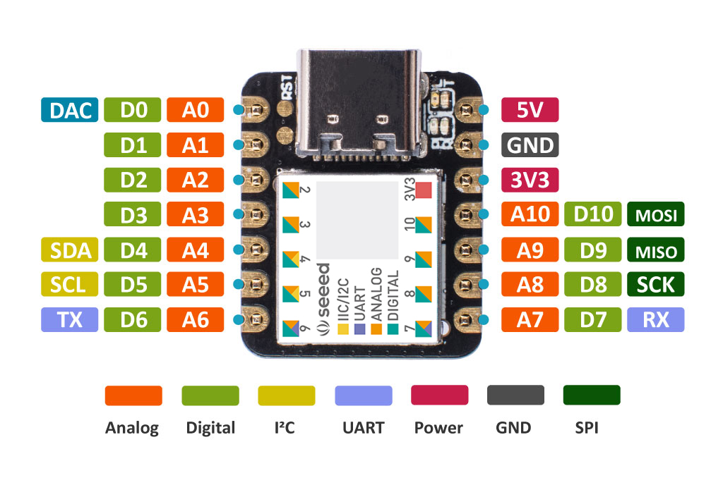
Connection:


Library:

In this exercise, adafruit_st7789 and adafruit_display_text of Adafruit CircuitPython Library Bundle is needed.

Visit https://circuitpython.org/libraries, download the appropriate bundle for your version of CircuitPython.

Unzip the file, copy adafruit_st7789.mpy and adafruit_display_text folder to the lib folder on your CIRCUITPY drive.

Example code:

Copy below examples code to code.py on CIRCUITPY drive to run.

spiST7789

"""
Example of CircuitPython/ESP32-S2 (run on nanoESP32-S2)
to display on 1.14" 135x240 (RGB) IPS screen
with ST7789 driver via SPI interface.

Connection between nanoESP32 and
the IPS screen, with ST7789 SPI interface.
3V3  - BLK (backlight, always on)
IO37 - CS
IO38 - DC
IO39 - RES
IO40 - SDA
IO41 - SCL
3V3  - VCC
GND  - GND
"""

import os
import board
import time
import terminalio
import displayio
import busio
from adafruit_display_text import label
#from adafruit_st7789 import ST7789
import adafruit_st7789

print("==============================")
print(os.uname())
print("Hello nanoESP32-S2/CircuitPython ST7789 SPI IPS Display")
print(adafruit_st7789.__name__ + " version: " + adafruit_st7789.__version__)
print()

# Release any resources currently in use for the displays
displayio.release_displays()

tft_cs = board.IO37
tft_dc = board.IO38
tft_res = board.IO39
spi_mosi = board.IO40
spi_clk = board.IO41

"""
classbusio.SPI(clock: microcontroller.Pin,
                MOSI: Optional[microcontroller.Pin] = None,
                MISO: Optional[microcontroller.Pin] = None)
"""
spi = busio.SPI(spi_clk, MOSI=spi_mosi)

display_bus = displayio.FourWire(
    spi, command=tft_dc, chip_select=tft_cs, reset=tft_res
)

#I get the parameters by guessing and trying
#display = ST7789(display_bus, width=135, height=240, rowstart=40, colstart=53)
display = adafruit_st7789.ST7789(display_bus,
                    width=135, height=240,
                    rowstart=40, colstart=53)

# Make the display context
splash = displayio.Group(max_size=10)
display.show(splash)

color_bitmap = displayio.Bitmap(135, 240, 1)
color_palette = displayio.Palette(1)
color_palette[0] = 0x00FF00

bg_sprite = displayio.TileGrid(color_bitmap, pixel_shader=color_palette, x=0, y=0)
splash.append(bg_sprite)

# Draw a smaller inner rectangle
inner_bitmap = displayio.Bitmap(133, 238, 1)
inner_palette = displayio.Palette(1)
inner_palette[0] = 0x0000FF
inner_sprite = displayio.TileGrid(inner_bitmap, pixel_shader=inner_palette, x=1, y=1)
splash.append(inner_sprite)

# Draw a label
text_group1 = displayio.Group(max_size=10, scale=2, x=20, y=40)
text1 = "ESP32-S2"
text_area1 = label.Label(terminalio.FONT, text=text1, color=0xFF0000)
text_group1.append(text_area1)  # Subgroup for text scaling
# Draw a label
text_group2 = displayio.Group(max_size=10, scale=1, x=20, y=60)
text2 = "CircuitPython"
text_area2 = label.Label(terminalio.FONT, text=text2, color=0xFFFFFF)
text_group2.append(text_area2)  # Subgroup for text scaling

# Draw a label
text_group3 = displayio.Group(max_size=10, scale=1, x=20, y=100)
text3 = adafruit_st7789.__name__
text_area3 = label.Label(terminalio.FONT, text=text3, color=0x0000000)
text_group3.append(text_area3)  # Subgroup for text scaling
# Draw a label
text_group4 = displayio.Group(max_size=10, scale=2, x=20, y=120)
text4 = adafruit_st7789.__version__
text_area4 = label.Label(terminalio.FONT, text=text4, color=0x000000)
text_group4.append(text_area4)  # Subgroup for text scaling

splash.append(text_group1)
splash.append(text_group2)
splash.append(text_group3)
splash.append(text_group4)

time.sleep(3.0)

rot = 0
while True:
    time.sleep(5.0)
    rot = rot + 90
    if (rot>=360):
        rot =0
    display.rotation = rot
    

spiST7789_bitmap
"""
Example of CircuitPython/ESP32-S2 (run on nanoESP32-S2)
to display on 1.14" 135x240 (RGB) IPS screen
with ST7789 driver via SPI interface.

Connection between nanoESP32 and
the IPS screen, with ST7789 SPI interface.
3V3  - BLK (backlight, always on)
IO37 - CS
IO38 - DC
IO39 - RES
IO40 - SDA
IO41 - SCL
3V3  - VCC
GND  - GND
"""

import os
import board
import time
import terminalio
import displayio
import busio
from adafruit_display_text import label
import adafruit_st7789

print("==============================")
print(os.uname())
print("Hello nanoESP32-S2/CircuitPython ST7789 SPI IPS Display")
print(adafruit_st7789.__name__ + " version: " + adafruit_st7789.__version__)
print()

# Release any resources currently in use for the displays
displayio.release_displays()

tft_cs = board.IO37
tft_dc = board.IO38
tft_res = board.IO39
spi_mosi = board.IO40
spi_clk = board.IO41

"""
classbusio.SPI(clock: microcontroller.Pin,
                MOSI: Optional[microcontroller.Pin] = None,
                MISO: Optional[microcontroller.Pin] = None)
"""
spi = busio.SPI(spi_clk, MOSI=spi_mosi)

display_bus = displayio.FourWire(
    spi, command=tft_dc, chip_select=tft_cs, reset=tft_res
)

display = adafruit_st7789.ST7789(display_bus,
                    width=135, height=240,
                    rowstart=40, colstart=53)
display.rotation = 270

group = displayio.Group(max_size=10)
display.show(group)

bitmap = displayio.Bitmap(240, 135, 135)

palette = displayio.Palette(135)
for p in range(135):
    palette[p] = (0x010000*p) + (0x0100*p) + p

for y in range(135):
    for x in range(240):
        bitmap[x,y] = y
        
tileGrid = displayio.TileGrid(bitmap, pixel_shader=palette, x=0, y=0)
group.append(tileGrid)

time.sleep(3.0)

while True:
    for p in range(135):
        palette[p] = p
    time.sleep(3.0)

    for p in range(135):
        palette[p] = 0x0100 * p
    time.sleep(3.0)

    for p in range(135):
        palette[p] = 0x010000 * p
    time.sleep(3.0)

spiST7789_terminal
"""
Example of CircuitPython/ESP32-S2 (run on nanoESP32-S2)
to display on 1.14" 135x240 (RGB) IPS screen
with ST7789 driver via SPI interface.

Connection between nanoESP32 and
the IPS screen, with ST7789 SPI interface.
3V3  - BLK (backlight, always on)
IO37 - CS
IO38 - DC
IO39 - RES
IO40 - SDA
IO41 - SCL
3V3  - VCC
GND  - GND
"""

import os
import board
import time
import terminalio
import displayio
import busio
from adafruit_display_text import label
#from adafruit_st7789 import ST7789
import adafruit_st7789

print("==============================")
print(os.uname())
print("Hello nanoESP32-S2/CircuitPython ST7789 SPI IPS Display")
print(adafruit_st7789.__name__ + " version: " + adafruit_st7789.__version__)
print()

# Release any resources currently in use for the displays
displayio.release_displays()

tft_cs = board.IO37
tft_dc = board.IO38
tft_res = board.IO39
spi_mosi = board.IO40
spi_clk = board.IO41

"""
classbusio.SPI(clock: microcontroller.Pin,
                MOSI: Optional[microcontroller.Pin] = None,
                MISO: Optional[microcontroller.Pin] = None)
"""
spi = busio.SPI(spi_clk, MOSI=spi_mosi)

display_bus = displayio.FourWire(
    spi, command=tft_dc, chip_select=tft_cs, reset=tft_res
)

#I get the parameters by guessing and trying
#display = ST7789(display_bus, width=135, height=240, rowstart=40, colstart=53)
display = adafruit_st7789.ST7789(display_bus,
                    width=135, height=240,
                    rowstart=40, colstart=53)
display.rotation = 270

"""
Now click on to activate Serial Console,
Press any key to enter the REPL.
You would have a terminal that you could type at and have the screen update.
"""


~ More example of ESP32-S2/CircuitPython

Saturday, December 12, 2020

nanoESP32-S2/CircuitPython: I2C and 128x64 SSD1306 OLED

Trying I2C on nanoESP32-S2/CircuitPython, and display on 128x64 OLED with I2C SSD1306 driver (3.3V), using adafruit_ssd1306.mpy and adafruit_framebuf.mpy of Adafruit CircuitPython Library Bundle.

Connection between nanoESP32-S2 and 128x64 I2C SSD1306 OLED:

ESP32-S2 - OLED
3V3 VCC
GND GND
IO40           SDA
IO41           SCL 

Exercise to 128x64 OLED with I2C SSD1306 driver:

import time
import os
import board
import busio
import adafruit_ssd1306
# lib needed:
# adafruit_ssd1306.mpy
# adafruit_framebuf.mpy

# Helper function to draw a circle from a given position with a given radius
# This is an implementation of the midpoint circle algorithm,
# see https://en.wikipedia.org/wiki/Midpoint_circle_algorithm#C_example for details
def draw_circle(xpos0, ypos0, rad, col=1):
    x = rad - 1
    y = 0
    dx = 1
    dy = 1
    err = dx - (rad << 1)
    while x >= y:
        display.pixel(xpos0 + x, ypos0 + y, col)
        display.pixel(xpos0 + y, ypos0 + x, col)
        display.pixel(xpos0 - y, ypos0 + x, col)
        display.pixel(xpos0 - x, ypos0 + y, col)
        display.pixel(xpos0 - x, ypos0 - y, col)
        display.pixel(xpos0 - y, ypos0 - x, col)
        display.pixel(xpos0 + y, ypos0 - x, col)
        display.pixel(xpos0 + x, ypos0 - y, col)
        if err <= 0:
            y += 1
            err += dy
            dy += 2
        if err > 0:
            x -= 1
            dx += 2
            err += dx - (rad << 1)
    display.show()

print("==============================")
print(os.uname())
print("Hello nanoESP32-S2/CircuitPython ssd1306 OLED example")
print(adafruit_ssd1306.__name__ + "version: " + adafruit_ssd1306.__version__)
print()

WIDTH = 128
HEIGHT = 64
CENTER_X = int(WIDTH/2)
CENTER_Y = int(HEIGHT/2)

SDA = board.IO40
SCL = board.IO41
i2c = busio.I2C(SCL, SDA)

if(i2c.try_lock()):
    print("i2c.scan(): " + str(i2c.scan()))
    i2c.unlock()

display = adafruit_ssd1306.SSD1306_I2C(WIDTH, HEIGHT, i2c)

display.fill(0)
display.show()
time.sleep(1.0)
display.fill(1)
display.show()
time.sleep(1.0)
display.fill(0)
display.show()
time.sleep(1.0)

for y in range(HEIGHT):
    for x in range(WIDTH):
        display.pixel(x, y, 1)
    display.show()
    
draw_circle(CENTER_X, CENTER_Y, 25, 0)

print("- bye -\n")

~ more exercises on nanoESP32-S2/CircuitPython.


Remark about ESP32-S2 pull-up resistor for I2C:

As mentioned in Espressif document ESP-IDF Programming Guide :  API Reference > Peripherals API > I2C DriverESP32-S2’s internal pull-ups are in the range of tens of kOhm, which is, in most cases, insufficient for use as I2C pull-ups. Users are advised to use external pull-ups with values described in the I2C specification.

As I understand, most I2C SSD1306 OLED module have pull-up resistors. It's no external resistor needed in this exercise.

Next:


Monday, December 7, 2020

nanoESP32-S2/CircuitPython exercise: to control external NeoPixel

Previous exercise show how to install Adafruit CircuitPython Library Bundle to nanoESP32-S2 dev. board, and drive the onboard NeoPixel. This post show how to drive external NeoPixel (Ring and Square).

IO45 is used to drive the 8X NeoPixel Ring. connect to its DI.
IO42 is used to drive the 4X4 NeoPixel Square, connect to its DI.
IO18 is used to drive the onboard NeoPixel.
In the exercise of ADCNeoPixel, IO1 is used as analog input, convert to digital and display on 8X NeoPixel Ring.

All the NeoPixels have color order of  GRB, so have to set pixel_order=neopixel.GRB.

Just copy the code to code.py on your nanoESP32-S2 board, save to run.

ADCNeoPixel.py
import time
import os
import microcontroller
import board
import analogio
import neopixel

adc01=analogio.AnalogIn(board.IO1)

NumOfPixel_ring = 8

def offAllPixel():
    pixel_ring.fill((0, 0, 0))
    onboard_pixel[0] = (0, 0, 0)
    pixel_ring.show()
    onboard_pixel.show()

print("==============================")
print(os.uname())
print("Hello nanoESP32-S2/CircuitPython NeoPixel/ADC example")
print("cpu.temperature: " + str(microcontroller.cpu.temperature))
print("neopixel version: " + neopixel.__version__)
print()

ref = adc01.reference_voltage
print("reference voltage: " + str(ref))

# Create the NeoPixel objects
# onboard NeoPixel = IO18
onboard_pixel = neopixel.NeoPixel(board.NEOPIXEL, 1, 
                    auto_write=False,
                    brightness=0.02,
                    pixel_order=neopixel.GRB)
                    
pixel_ring = neopixel.NeoPixel(board.IO45, NumOfPixel_ring, 
                    auto_write=False,
                    brightness=0.3,
                    pixel_order=neopixel.GRB)

offAllPixel()
#blink neopixels to start
time.sleep(0.5)
onboard_pixel[0] = (255, 0, 0)
onboard_pixel.show()
time.sleep(0.5)
onboard_pixel[0] = (0, 255, 0)
onboard_pixel.show()
time.sleep(0.5)
onboard_pixel[0] = (20, 0, 255)
onboard_pixel.show()
time.sleep(0.5)
onboard_pixel[0] = (0, 0, 0)
onboard_pixel.show()

pixel_ring.fill((0, 0, 0))
pixel_ring.show()
time.sleep(1.0)

while True:
    value01=adc01.value
    step = int(value01/8192)
    offAllPixel()
    for i in range(step):
        pixel_ring[i] = (255, 255, 255)
    pixel_ring.show()
    
    onboard_pixel.brightness = step/10
    onboard_pixel[0] = (0, 0, 255)
    onboard_pixel.show()

    time.sleep(0.1)

print("- bye -\n")


testNeopixel.py
import time
import os
import microcontroller
import neopixel
import board
import random

NumOfPixel_ring = 8
NumOfPixel_sq = 16

def offAllPixel():
    fillAllPixel(0, 0, 0)
    
def fillAllPixel(r, g, b):
    pixel_ring.fill((r, g, b))
    pixel_sq.fill((r, g, b))
    onboard_pixel[0] = (r, g, b)


print("==============================")
print(os.uname())
print("Hello nanoESP32-S2/CircuitPython NeoPixel example")
print("Test on:")
print("Onboard NEOPIXEL")
print("8X NeoPixel Ring")
print("4X4 NeoPixel Square")
print("cpu.temperature: " + str(microcontroller.cpu.temperature))
print()
print("neopixel version: " + neopixel.__version__)
print()

# Create the NeoPixel objects
# onboard NeoPixel = IO18
onboard_pixel = neopixel.NeoPixel(board.NEOPIXEL, 1, 
                    brightness=0.1,
                    pixel_order=neopixel.GRB)
                    
pixel_ring = neopixel.NeoPixel(board.IO45, NumOfPixel_ring, 
                    brightness=0.1,
                    pixel_order=neopixel.GRB)
                    
pixel_sq = neopixel.NeoPixel(board.IO42, NumOfPixel_sq, 
                    brightness=0.1, pixel_order=neopixel.GRB)

offAllPixel()

#blink neopixels to start
time.sleep(0.5)
onboard_pixel[0] = (255, 0, 0)
time.sleep(0.5)
onboard_pixel[0] = (0, 255, 0)
time.sleep(0.5)
onboard_pixel[0] = (20, 0, 255)
time.sleep(0.5)
onboard_pixel[0] = (0, 0, 0)

for i in range(NumOfPixel_ring):
    pixel_ring.fill((0, 0, 0))
    pixel_ring[i] = (255, 255, 255)
    time.sleep(0.5)
pixel_ring.fill((0, 0, 0))

for i in range(NumOfPixel_sq):
    pixel_sq.fill((0, 0, 0))
    pixel_sq[i] = (255, 255, 255)
    time.sleep(0.5)
pixel_sq.fill((0, 0, 0))
time.sleep(0.5)

fillAllPixel(255, 0, 0)
time.sleep(1.0)
fillAllPixel(0, 255, 0)
time.sleep(1.0)
fillAllPixel(0, 0, 255)
time.sleep(1.0)

offAllPixel()
time.sleep(2.0)

print("- bye -\n")

randomNeopixel.py
import time
import os
import microcontroller
import neopixel
import board
import random

NumOfPixel_ring = 8
NumOfPixel_sq = 16

def offAllPixel():
    fillAllPixel(0, 0, 0)
    
def fillAllPixel(r, g, b):
    pixel_ring.fill((r, g, b))
    pixel_sq.fill((r, g, b))
    onboard_pixel[0] = (r, g, b)
    
def randomNeopixel():

    for r in range(2000):
        r = random.randint(0, 255)
        g = random.randint(0, 255)
        b = random.randint(0, 255)
        
        onboard_pixel[0] = (r, g, b)
        i = random.randint(0, NumOfPixel_ring-1)
        pixel_ring[i] = (r, g, b)
        i = random.randint(0, NumOfPixel_sq-1)
        pixel_sq[i] = (r, g, b)
        
        time.sleep(0.2)


print("==============================")
print(os.uname())
print("Hello nanoESP32-S2/CircuitPython NeoPixel example")
print("Generate random color on:")
print("Onboard NEOPIXEL")
print("8X NeoPixel Ring")
print("4X4 NeoPixel Square")
print("cpu.temperature: " + str(microcontroller.cpu.temperature))
print()
print("neopixel version: " + neopixel.__version__)
print()

# Create the NeoPixel objects
# onboard NeoPixel = IO18
onboard_pixel = neopixel.NeoPixel(board.NEOPIXEL, 1, 
                    brightness=0.05,
                    pixel_order=neopixel.GRB)
                    
pixel_ring = neopixel.NeoPixel(board.IO45, NumOfPixel_ring, 
                    brightness=0.05,
                    pixel_order=neopixel.GRB)
                    
pixel_sq = neopixel.NeoPixel(board.IO42, NumOfPixel_sq, 
                    brightness=0.05, pixel_order=neopixel.GRB)

offAllPixel()

#blink neopixels to start
time.sleep(0.5)
onboard_pixel[0] = (255, 0, 0)
time.sleep(0.5)
onboard_pixel[0] = (0, 255, 0)
time.sleep(0.5)
onboard_pixel[0] = (20, 0, 255)
time.sleep(0.5)
onboard_pixel[0] = (0, 0, 0)

randomNeopixel()

offAllPixel()
time.sleep(2.0)

print("- bye -\n")


Related:

Sunday, December 6, 2020

nanoESP32-S2/CircuitPython exercise: ADC (Analog to Digital Converter)

This exercise run on nanoESP32-S2/CircuitPython, read analog input from IO1, and convert to voltage. Then display on Mu editor's Plotter.

import time
import os
import microcontroller
import board
import analogio

adc01=analogio.AnalogIn(board.IO1)

print("==============================")
print(os.uname())
print("Hello nanoESP32-S2/CircuitPython ADC example")
print("cpu.temperature: " + str(microcontroller.cpu.temperature))
print()

ref = adc01.reference_voltage
print("reference voltage: " + str(ref))

while True:
    value01=adc01.value
    voltage = ref * value01/65535
    print((ref, voltage))
    time.sleep(0.5)

print("- bye -\n")


remark:
As shown in the video, the ADC measured voltage cannot reached 3.3V.
 
I checked the voltage on IO1, is 3.3V. But the returned value of adc01 (analogio.AnalogIn(board.IO1)) is 51871, correspond 2.6V.
 

To get the reference voltage used by the ADC, e can read the property analogio.AnalogIn.reference_voltage.

For ADC values in CircuitPython you’ll find they’re all put into the range of 16-bit unsigned values. This means the possible values you’ll read from the ADC fall within the range of 0 to 65535 (or 2^16 - 1).

(ref: CircuitPython Basics: Analog Inputs & Outputs > Analog to Digital Converter (Inputs))


Next:

Saturday, December 5, 2020

TinyML: Using Machine Learning on Microcontroller to recognize speech@Remoticon 2020


Running a neural network on a micro-controller might seem absurd, but it’s possible (and has some great uses!). In this workshop, we’ll train a neural network to recognize one of several spoken words, convert it to a TensorFlow Lite model, and load it onto an ARM micro-controller (STM32 Nucleo-L476RG board), where it will listen for and respond to the wake word in real-time. Prior knowledge of machine learning is not necessary for this workshop, but it can be helpful to understand how the neural network operates.

Instructor: Shawn Hymel
Shawn is an electrical and embedded engineer, freelance content creator, and instructor. He and Harris Kenny host the podcast, Hello Blink Show, where they discuss various aspects of starting a business from sales to marketing to hiring. From 2013 to 2018, Shawn worked for SparkFun Electronics designing open-source PCBs, writing firmware, teaching concepts on video, and creating tutorials. Shawn started his own company, Skal Risa, LLC, to help companies create compelling technical content in electronics and embedded systems. He is also an advocate for enriching education through STEM and believes that the best marketing comes from teaching. He can be found giving talks, running workshops, and swing dancing in his free time.

Read the article on Hackaday:
https://hackaday.com/?p=450862

All example code and slides:
https://github.com/ShawnHymel/ei-keyword-spotting

Workshop project page:
https://hackaday.io/project/175078-remoticon-tiny-ml

Music by Rich Hogben


Friday, December 4, 2020

Mu editor Plotter

The Plotter of Mu editor is a graph tool to visualise numeric data which your code may create.

To activate the plotter in those modes that support it, simply toggle it on or off by clicking the “Plotter” button.

When the plotter is active it begins to listen for a valid source of data. This could be your Python program, something in the REPL or serial data coming from a connected device.

In all instances the pattern of valid data is the same: a Python tuple containing only numeric data printed to a new line. In case you’re wondering, a tuple in Python is a collection of data enclosed by parentheis, and looks like this: (1, 2, 3).

Each item in the tuple will be plotted on a separate line in the line chart. So, if you have three sources of data, each time you emit a tuple it will have three numbers in it, one for each source of data.


CircuitPython 6.1.0 Beta 2 released

CircuitPython 6.1.0 Beta 2 is released (2020-12-03). The downloads page is here, select the correct file and language for your board. 

As mentioned in the Release Notes for 6.1.0-beta.2, Please use 6.0.x if you need a stable version of CircuitPython on all ports except ESP32-S2. Please use this release or newer for the ESP32-S2

To Install CircuitPython to nanoESP32-S2, refer here.

For more exercise of using ESP32-S2, refer here.

Saturday, November 28, 2020

nanoESP32-S2/CircuitPython control on-board NeoPixel, using Adafruit CircuitPython Library Bundle

With CircuitPython installed to nanoESP32-S2, we are going to program nanoESP32-S2 with CircuitPython, using neopixel library come from Adafruit CircuitPython Library Bundle.


The CircuitPython Library Bundle contains all current libraries available for CircuitPython.

To use neopixel library, we have to install Adafruit CircuitPython Library Bundle to our CircuitPython board, nanoESP32-S2. 

- Visit CircuitPython Libraries, download the appropriate bundle for your version of CircuitPython, it is adafruit-circuitpython-bundle-6.x-mpy-20201126.zip in my case. Unzip the file, open the resulting folder and find the lib folder. Open the lib folder and find the library files you need to load. Copy the individual library files you need to the lib folder on your CIRCUITPY drive.

- And we have to check the IO assigned to nanoESP32-S2 on-board NeoPixel.
Visit GitHub wuxx/nanoESP32-S2/schematic/nanoESP32S2-v1.2.pdf to check the schematic. 

Found that the IO assigned to DIN of WS2812B is GPIO18, board.IO18 in CircuitPython.  Actually, board.NEOPIXEL is defined as board.IO18.

WS2812B is a intelligent control LED light source that the control circuit and RGB chip are integrated in a package of 5050 components, the NeoPixel.

- Edit code.py in CIRCUITPY, save and run it:
import time
import os
import microcontroller
import neopixel
import board

def cycleNeopixel(wait):
    for r in range(255):
        pixel[0] = (r, 0, 0)
        time.sleep(wait)
    for r in range(255, 0, -1):
        pixel[0] = (r, 0, 0)
        time.sleep(wait)
        
    for g in range(255):
        pixel[0] = (0, g, 0)
        time.sleep(wait)
    for g in range(255, 0, -1):
        pixel[0] = (0, g, 0)
        time.sleep(wait)
        
    for b in range(255):
        pixel[0] = (0, 0, b)
        time.sleep(wait)
    for b in range(255, 0, -1):
        pixel[0] = (0, 0, b)
        time.sleep(wait)
        
print("==============================")
print(os.uname())
print("Hello nanoESP32-S2/CircuitPython NeoPixel example")
print("cpu.temperature: " + str(microcontroller.cpu.temperature))
print()
print("neopixel version: " + neopixel.__version__)
print()

# Create the NeoPixel object
pixel = neopixel.NeoPixel(board.IO18, 1, pixel_order=neopixel.RGB)
pixel[0] = (0, 0, 0)
time.sleep(2.0)

cycleNeopixel(0.01)

pixel[0] = (0, 0, 0)
time.sleep(2.0)

print("- bye -\n")


Check in the video:


It seem R and G is swapped in my unit, it should be GRB order for the build-in NeoPixel. To correct it, have to change "pixel_order=neopixel.RGB" to "pixel_order=neopixel.GRB" to match. It will be fixed in next exercise.

Next:

Wednesday, November 25, 2020

Hello ESP32-S2/CircuitPython, on nanoESP32-S2

To install CircuitPython to nanoESP32-S2 (run on Raspberry Pi), refer to my another post: Hello Raspberry Pi - Install CircuitPython to nanoESP32-S2, on Raspberry Pi.


How to run code.py on nanoESP32-S2/CircuitPython, in Mu editor:

When CircuitPython finishes installing, or you plug a CircuitPython board into your computer with CircuitPython already installed, the board shows up on your computer as a USB drive called CIRCUITPY.

The CIRCUITPY drive is where your code and the necessary libraries and files will live. You can edit your code directly on this drive and when you save, it will run automatically. When you create and edit code, you'll save your code in a code.py file located on the CIRCUITPY drive.

CircuitPython looks for code.py and runs the contents of the file automatically when the board starts up, reloads, or when you save changes to the file.


This video show how to run code.py on nanoESP32-S2/CircuitPython, in Mu editor:


More related to CircuitPython/ESP32-S2:

Updated for CircuitPython 7

Monday, November 23, 2020

ESP32-S2 dev. board: ESP32-S2-Saola-1 and nanoESP32-S2

ESP32-S2 is a highly integrated, low-power, single-core Wi-Fi Microcontroller SoC, designed to be secure and cost-effective, with a high performance and a rich set of IO capabilities. They are an ideal choice for a wide variety of application scenarios relating to the Internet of Things (IoT), wearable electronics and smart home. (ref: https://www.espressif.com/en/products/socs/esp32-s2)

Currently, it have 6 modules include:

My boards with ESP32-S2 Module: ESP32-S2-Saola-1 and nanoESP32-S2


My ESP32-S2-Saola-1 (with ESP32-S2-WROVER module):


ESP32-S2-Saola-1 is a small-sized ESP32-S2 based development board produced by Espressif.

It currently support:

WROOM: no PSRAM
WROVER: with PSRAM
-I: IPEX Antenna
without -I: PCB Antenna

My unit have ESP32-S2-WROVER (PCB Antenna, with PSRAM) module.


My nanoESP32-S2 (with ESP32-S2-WROVER-I module):


nanoESP32-S2 is another development board of ESP32-S2 produced by museLab. It support the four modules also, ESP32-S2-WROVER, ESP32-S2-WROVER-I, ESP32-S2-WROOM and ESP32-S2-WROOM-I.

One advantage of this board is it have a extra USB port (marked "esp32"), connect to ESP32-S2 chip directly. It is more easy to develop using CircuitPython.

My unit come with ESP32-S2-WROVER-I module (IPEX Antenna, with PSRAM) module.


Next:


Monday, November 16, 2020

Install esptool on Raspberry Pi OS (32 bit)

esptool.py is a Python-based, open source, platform independent, utility to communicate with the ROM bootloader in Espressif ESP8266 & ESP32 chips, and also ESP32-S2.

To install on Raspberry Pi (running 32 bit Raspberry Pi OS), open Terminal and enter the command:

$ sudo pip install esptool

or install Development mode, allows you to run the latest development version from this repository.

$ git clone https://github.com/espressif/esptool.git
$ cd esptool
$ pip install --user -e .


Monday, November 9, 2020

Yahboom K210 Developer Kit, to learn Al vision technology

This Yahboom K210 Developer Kit is a small full-featured development board kit developed by Yahboom and Canaan. The RISC-V processor structure adopted by K210 is specially designed for machine vision and machine hearing multi-mode shape recognition, it can be widely used in smart home, machine vision, intelligent robots, security monitoring and other fields. The development board not only contains a variety of peripherals such as capacitive touch screen,camera, micro-phone,speaker, six-axis aittitude sensor, and WIFl module, but also provides rich development materials to facilitate secondary development and learning, and lower the threshold for learning Al vision technology.

details: ~ K210 Developer Kit repository


Thursday, October 8, 2020

Bluetooth Serial communication between HC-08(Master) and HC-04(Slave)


This video show testing Bluetooth Serial communication between BT modules HC-08(in Master role) and HC-04(in Slave role). Seeeduino XIAO is programmed as USB-to-Serial bridge between host (Raspberry Pi in this example) and HC-08.


Link:


Monday, September 28, 2020

Seeeduino XIAO display on OLED screen (with ssd1306 using I2C interface)

This example show how Seeeduino XIAO display on OLED screen, with ssd1306 driver using I2C interface, using ssd1306 library.

Connection between XIAO and OLED (ssd1306)
XIAO		OLED (ssd1306 I2C)
3V3			VCC
GND			GND
SDA			SDA
SCL			SCL

Make sure Seeed SAMD Boards is installed in Boards Manager, refer to the post Seeeduino XIAO for Install Seeeduino XIAO board to Arduino IDE.


Make sure ssd1306 library is installed in Library Manager.


Select board of Seeeduino XIAO


Confirm port


Open ssd1306_demo example


Thursday, September 17, 2020

Program Seeeduino XIAO as USB-to-Serial bridge, to access HC-08 BLE 4.0 Module/ESP WiFi Modules.


HC-08 is a Bluetooth 4.0 low energy module. It provide TTL Serial interface. If we want to access it using PC, normal a USB-to-Serial adapter is used.

In this exercise, Seeeduino XIAO is programmed as a USB-to-Serial bridge to read/write HC-08 from Raspberry Pi using Arduino IDE's Serial Monitor.

Connection between Seeeduino XIAO and HC-08

XIAO		HC-08
=====================
3V3		VCC
GND		GND
TX		RX
RX		TX

For the code, simple foreward date from SerialUSB to Serial1, and foreward Serial1 to SerialUSB.

X_USBbridge.ino

/*
Xiao act as a bridge between USB and Serial device

It's assumed the device is running 3V3
Connection
Xiao Rx   - device Tx
Xiao Tx   - device Rx
XIAO GND  - device GND
XIAO 3V3  - device VCC

*/

void setup()
{
  pinMode(LED_BUILTIN, OUTPUT);
  
  delay(1000);
  SerialUSB.begin(9600);
  Serial1.begin(9600);

  //wait serial ports to device
  //while(SerialUSB);
  while(!Serial1);
  
  //Blink the LED 3 times to indicate program started
  for(int i=0; i<3; i++){
    digitalWrite(LED_BUILTIN, HIGH);
    delay(500);
    digitalWrite(LED_BUILTIN, LOW);
    delay(500);
  }
}

void loop()
{
  if(SerialUSB.available() > 0){
    Serial1.write(SerialUSB.read());
  }

  if(Serial1.available() > 0){
    SerialUSB.write(Serial1.read());
  }
}

This video show how it work.

Before HC-08 connected (LED blinking), You can read/write HC-08 status with AT Command.
After HC-08 connected with test app on Android phone (LED on), you can send/receive text to/from the app. 

To know where/how to download datasheet (with AT Command Set) and test app for HC-08, read the post "HC-08 Bluetooth Module (BLE 4.0)".

To install Seeeduino XIAO board to Arduino IDE, read the post "Seeeduino XIAO".


This can be used to access HC-04 Dual Mode BLE SPP Bluetooth Module also.


Next:


Access ESP WiFi Modules:

With baud rate changed to 115200, it can access ESP WiFi modules. Tested with ESP-01S and ESP-12S.

X_USBbridge_115200.ino

/*
Xiao act as a bridge between USB and Serial device

It's assumed the device is running 3V3
Connection
Xiao Rx   - device Tx
Xiao Tx   - device Rx
XIAO GND  - device GND
XIAO 3V3  - device VCC

*/

void setup()
{
  pinMode(LED_BUILTIN, OUTPUT);
  
  delay(1000);
  SerialUSB.begin(115200);
  Serial1.begin(115200);

  //wait serial ports to device
  //while(SerialUSB);
  while(!Serial1);
  
  //Blink the LED 3 times to indicate program started
  for(int i=0; i<3; i++){
    digitalWrite(LED_BUILTIN, HIGH);
    delay(500);
    digitalWrite(LED_BUILTIN, LOW);
    delay(500);
  }
}

void loop()
{
  if(SerialUSB.available() > 0){
    Serial1.write(SerialUSB.read());
  }

  if(Serial1.available() > 0){
    SerialUSB.write(Serial1.read());
  }
}


Arduino IDE run on Raspberry Pi, to program Xiao as bridge to access ESP-01S:


Sunday, September 13, 2020

Seeeduino XIAO

The Seeeduino XIAO is a tiny microcontroller board with powerful cpu SAMD21G18, ARM® Cortex®-M0+ 32bit 48MHz microcontroller with 256KB Flash,32KB SRAM.


Seeeduino XIAO has 14 GPIO PINs, which can be used for 11 digital interfaces, 11 mock interfaces, 10 PWM interfaces (d1-d10), 1 DAC output pin D0, 1 SWD pad interface, 1 I2C interface, 1 SPI interface, 1 UART interface, Serial communication indicator (T/R), Blink light (L). The colors of LEDs(Power,L,RX,TX) are green, yellow, blue and blue. Moreover, Seeeduino XIAO has a Type-C interface which can supply power and download code. There are two reset pad, you can short connect them to reset the board.

Pinout:


Install Seeeduino XIAO board to Arduino IDE

With Arduino IDE installed, 
- select menu File > Preference, 
- add Additional Boards Manager URLs with: 
https://files.seeedstudio.com/arduino/package_seeeduino_boards_index.json

- Tools-> Board-> Boards Manager...
- Search "Seeeduino XIAO"
- Install "Seeed SAMD Boards"

Product page: Seeed Wiki - Seeeduino XIAO

Next:


HC-08/HC-04 Bluetooth Module

HC-08 Bluetooth Module (BLE 4.0)


HC-08 is a Bluetooth 4.0 low energy module, it can easily connect to iOS 5 and Android 4.3 or above by using a serial terminal app. You can use the Bluetooth communication up to 87 yards (80 meters) with this Bluetooth BLE module. It also runs on a 2.4GHz frequency. The chipset is CC2540 with 256K Byte space. You can change the role and serial baud rate and it supports AT commands for configuration.

It is very small in size, 1.1 x 0.5 in (26.9 x 13mm). The PCB thickness is 0.03 (0.7mm). Half-cut holes run along the lengths of the board, so it’s very easy to embed into your own project. It also has Tx and Rx 2.54 pin out, from which you can do a quick function test. Included are 90-degree male header pins.

HC-08 is a relatively new module made by an experienced Bluetooth design and manufacturing supplier in China. It’s mass produced and therefore well-tested. It can be incorporated into products or projects without worrying about being able to get it again. It’s already widely used in many Bluetooth projects.

Product page: http://www.hc01.com/products/6 (in Chinese)


This video show how to download and run test app for HC-08 Bluetooth module, and also download datasheet with AT command set.

In the testing, a wire is used to connect between HC-08 TX and RX pins, such that the message sent will be echo back.


Summary of AT Command Set in the datasheet is captured here.


HC-04 Dual Mode BLE SPP Bluetooth Module

HC-04 Bluetooth serial communication module is a new generation of dual-mode digital transmission module based on V2.1 (SPP) classic Bluetooth protocol and V4.0 (BLE) Bluetooth protocol. Only supports slave mode.


Friday, September 11, 2020

MicroPython on pyboard to display text on OLED (with I2C interface ssd1306)

It's a 0.96 inch 128x64  OLED displays with ssd1306 driver using I2C interface. This example show how to display text on it with pyboard using MicroPython ssd1306 library.

Connection between pyboard and OLED:
pyboard 3V3 connected to ssd1306 VCC
pyboard GND connected to ssd1306 GND
pyboard X12 connected to ssd1306 SCL
pyboard X11 connected to ssd1306 SDA


Download the MicroPython ssd1306 library HERE, ans save it to pyboard flash.

MicroPython script, pyb_i2c_ssd1306.py:

# Download ssd1306
# https://github.com/micropython/micropython/blob/master/drivers/display/ssd1306.py
# and save to pyboard flash

import ssd1306
import machine
import time

WIDTH = const(128)
HEIGHT = const(64)

ssd1306_scl = machine.Pin('X12', machine.Pin.OUT_PP)
ssd1306_sda = machine.Pin('X11', machine.Pin.OUT_PP)
i2c_ssd1306 = machine.I2C(scl=ssd1306_scl, sda=ssd1306_sda)

print(i2c_ssd1306.scan())
oled = ssd1306.SSD1306_I2C(WIDTH, HEIGHT, i2c_ssd1306)
oled.fill(0)

oled.text("MicroPython", 0, 0)
oled.text("OLED(ssd1306)", 0, 10)
oled.text("pyboard", 0, 20)
oled.show()

while True:
    time.sleep(1)
    oled.invert(1)
    time.sleep(1)
    oled.invert(0)


pyboard MicroPython exercise: scan I2C address

 It's a MicroPython exercise running on pyboard, to scan I2C address of attached I2C device. Actually, the I2C device used is a OLED with I2C interface ssd1306 in next exercise.

i2c_scan.py

#I2C SCL connected to pyboard X12
#I2C SDA connected to pyboard X11

import machine
i2c_scl = machine.Pin('X12', machine.Pin.OUT_PP)
i2c_sda = machine.Pin('X11', machine.Pin.OUT_PP)

i2c = machine.I2C(scl=i2c_scl, sda=i2c_sda)
print(i2c.scan())


Monday, September 7, 2020

Modified MicroPython pyboard PYBv1.1, and more...


It's a modified version of MicroPython pyboard, PYBv1.1, with extra modification:
- BOOT0 button for enter DFU mode, such that you no need to use a wire to connect P1 and 3V3.
- SWD connetor
- PWR LED


Getting pyboard MicroPython REPL using Thonny, on Ubuntu 20.04


To install Thonny on Ubuntu 20.04 and add USB permission to user, read the post "Install esptool/thonny on Ubuntu 20.04". (No need to install esptool if you target not for ESP devices such as ESP8266/ESP32)

Run Thonny
> Run > Select interpreter...
> Select MicroPython (generic) and connected USB Port

Run MicroPython script using Thonny IDE


Update MicroPython firmware on pyboard

A list of all available firmware is here.
In my case, it's pybv11-20200902-v1.13.dfu.

To update pyboard MicroPython firmware on Ubuntu, have to install dfu-util:
$ sudo apt update
$ sudo apt install dfu-util

First, disconnect everything from your pyboard. Then connect the DFU pin with the 3.3V pin (they're right next to each other) to put the board into DFU (Device Firmware Update) mode, or press and hold the BOOT0 button for my Modified MicroPython pyboard PYBv1.1. Now connect the pyboard to your computer via USB.

Update firmware using dfu-util:
$ sudo dfu-util --alt 0 -D <downloaded dfu file>

After the the program finished, disconnect the pyboard from USB and remove the jumper between the DFU and the 3.3v ports.


MicroPython firmware updated


Related:

Sunday, September 6, 2020

Sipeed Maix Amigo


SIPEED Maix Amigo is an all-in-one programmable AIoT development kit that can be used for AI and IoT learning. It has a built-in RV64GC RISC-V 64-bit 400Mhz dual-core high-performance processor with 8M on-chip SRAM and 16MiB FLASH storage. It is equipped with 2 cameras, TF card slot, user buttons, TFT capacitive touch screen, lithium battery, speaker, microphone, 2 USB ports, and an expansion interface.


Related links:
- Official MaixPy Documentation website: https://maixpy.sipeed.com/
- Download site: https://dl.sipeed.com/
- Sipeed programming guide: https://wiki.sipeed.com/

- Seeed Studio's Sipeed Maix Amigo page - Sipeed Maix Amigo - All-in-One AIoT Development Platform Based on RV64GC (RISC-V)