Adsense HTML/JavaScript

Showing posts with label Seeeduino XIAO. Show all posts

Friday, March 12, 2021

Simple test DX-BT24 (BLE 5.0 Bluetooth module), with Seeeduino XIAO as serial bridge.

DX-BT24 is a BLE 5.0 Bluetooth module with UART interface. Seeeduino XIAO is programmed (in Arduino platform) as a serial bridge to link Arduino Serial Monitor and DX-BT24. The another side, Serial Bluetooth Terminal app (on Android) is used to test with.

/*
Xiao act as a bridge between USB and BT-24

The device (BT-24) is powered on 3V3
Connection
Xiao Rx   - device Tx
Xiao Tx   - device Rx
XIAO GND  - device GND
XIAO 3V3  - device VCC
XIAO D1   - STATE

*/

const int PIN_STATE = 1;


void setup()
{
  pinMode(LED_BUILTIN, OUTPUT);
  pinMode(PIN_STATE, INPUT);
  
  delay(1000);
  SerialUSB.begin(9600);
  Serial1.begin(9600);

  //wait serial ports to device
  //while(SerialUSB);
  while(!Serial1);
  
  //Blink the LED 3 times to indicate program started
  for(int i=0; i<3; i++){
    digitalWrite(LED_BUILTIN, HIGH);
    delay(500);
    digitalWrite(LED_BUILTIN, LOW);
    delay(500);
  }
}

void loop()
{
  if(SerialUSB.available() > 0){
    Serial1.write(SerialUSB.read());
  }

  if(Serial1.available() > 0){
    SerialUSB.write(Serial1.read());
  }


  if (digitalRead(PIN_STATE) == HIGH){
    digitalWrite(LED_BUILTIN, LOW);
  }else{
    digitalWrite(LED_BUILTIN, HIGH);
  }
  
}


link:
~ DX-BT24 product page


Wednesday, March 10, 2021

ESP_AT_Lib tested on XIAO with ESP32-S


ESP_AT_Lib is an ESP8266/ESP32 wrapper library for Arduino providing an easy-to-use way to manipulate ESP8266/ESP32-AT shields. Test on Seeeduino XIAO (programmed in Arduino framework) with ESP32-S. ESP32-S is act as a WiFi co-processor, controlled using AT-command. 

ESP_AT_Lib can be installed in Arduino IDE's Library Manager.


Try ESP_AT_Lib example ConnectWiFi


Uncomment the code "#define USE_ESP32_AT true" to use ESP32-AT commands.


Edit ssid/password for your WiFi network.


Here is the running output:


About ESP32-S/and ESP-AT:

ESP32-S is a wireless module based on ESP32, supports WiFi and Bluetooth 4.2, with built-in 32Mbit Flash, in the SMD38 package. There're also onboard PCB antenna and metal shield. In short, it's a small form factor and fairly high cost effective wireless module.

ESP32-S used is flashed  with ESP-AT Firmware, of version:
AT version:2.1.0.0(883f7f2 - Jul 24 2020 11:50:07)
SDK version:v4.0.1-193-ge7ac221
compile time(0ad6331):Jul 28 2020 02:47:21
Bin version:2.1.0(WROOM-32)

What is ESP-AT:

ESP-AT is a solution developed by Espressif to integrate connectivity into customers’ products, which can be quickly moved to mass production. It aims to reduce software development costs and quickly form products. With ESP-AT commands, you can quickly join the wireless network, connect to the cloud platform, realize data transmission and remote control functions, and realize the interconnection of everything through wireless communication easily.

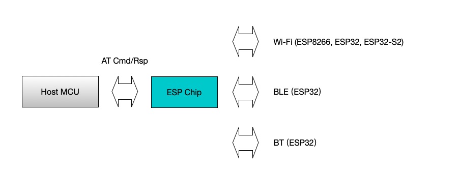
ESP-AT is a project based on ESP-IDF or ESP8266_RTOS_SDK. It makes an ESP board work as a slave, and an MCU as a host. The host MCU sends AT commands to the ESP chip and receives AT responses back. ESP-AT provides a wide range of AT commands with different functions, such as Wi-Fi commands, TCP/IP commands, Bluetooth LE commands, Bluetooth commands, MQTT commands, HTTP commands, and Ethernet commands.


Please note that ESP32 AT uses two UART ports: UART0 is used to download firmware and log output; UART1 is used to send AT commands and receive AT responses.

All ESP32 modules use GPIO1 and GPIO3 as UART0, but they use different GPIOs as UART1. The following sections illustrate which GPIOs you should connect for each ESP32 series of modules.


In my case:
XIAO TX connect to GPIO16 (RX)
XIAO RX connect to GPIO17 (TX)
Wthout hardware flow control., just ignore CTS/RTS.

Suggested to provide separated power supply to ESP32:

At beginning, I power the ESP32-S module from XIAO 3V3. But it re-boot repeatedly, caused by:
Brownout detector was triggered

It's caused by power low. With separated power from breadoard power supply to ESP32-S, this problem fixed.

Thursday, February 11, 2021

Test AHT20+BMP280 Temperature, Humidity and Pressure Sensor Module on Seeeduino XIAO with SSD1306 I2C OLED

AHT20+BMP280 Digital Temperature, Humidity and Pressure Sensor Module
It's a module adopts the digital temperature and humidity sensor AHT20 and Bosch BPM280 composed of Aosong, I2C mainstream output,


This post test it on Seeeduino XIAO with SSD1306 I2C OLED, in Arduino framework.


Connection:


Library:

To install SSD1306 library on Arduino IDE, refer to the post "Seeeduino XIAO display on OLED screen (with ssd1306 using I2C interface)".

For AHT20+BMP280,  AHTX0 and BMP280 libraries by Adafruit will be used, both them can be installed in Arduino IDE Library Manager.


AHT20 Testing:

X_AHT20_ssd1306.ino, modified from Examples > Adafruit AHTX0 > adafruit_aht_test.
#include "ssd1306.h"
#include <Adafruit_AHTX0.h>

Adafruit_AHTX0 aht;

void setup() {

  Serial.begin(9600);
  Serial.println("AHT20 test");

  if (! aht.begin()) {
    Serial.println("Could not find AHT? Check wiring");
    while (1) delay(10);
  }
  Serial.println("AHT10 or AHT20 found");
  
  ssd1306_setFixedFont(ssd1306xled_font6x8);
  ssd1306_128x64_i2c_init();
  ssd1306_clearScreen();
  ssd1306_printFixed(0,  8, "arduino-er exercise", STYLE_NORMAL);
  ssd1306_printFixed(0, 16, "XIAO/ssd1306", STYLE_BOLD);
  ssd1306_printFixed(0, 24, "AHT20 test", STYLE_ITALIC);
  ssd1306_positiveMode();

  delay(2000);
  ssd1306_clearScreen();
}

void loop() {
  sensors_event_t humidity, temp;
  aht.getEvent(&humidity, &temp);// populate temp and humidity objects with fresh data
  Serial.print("Temperature: "); 
  Serial.print(temp.temperature); 
  Serial.println(" degrees C");

  ssd1306_printFixed(0, 10, "- AHT20 -", STYLE_BOLD);
  
  char charTemp[32];
  dtostrf(temp.temperature, 8, 2, charTemp);
  ssd1306_printFixed(0, 28, "Temperature (C):", STYLE_NORMAL);
  ssd1306_printFixed(80, 36, charTemp, STYLE_NORMAL);
  
  Serial.print("Humidity: "); 
  Serial.print(humidity.relative_humidity); 
  Serial.println("% rH");

  char charHumi[32];
  dtostrf(humidity.relative_humidity, 8, 2, charHumi);
  ssd1306_printFixed(0, 44, "Humidity (% rH):", STYLE_NORMAL);
  ssd1306_printFixed(80, 52, charHumi, STYLE_NORMAL);

  delay(500);
}


BMP280 Testing:

X_BMP280_ssd1306.ino, modified from Examples > Adafruit BMP280 Library > bmp280test.
#include "ssd1306.h"
#include <Wire.h>
#include <SPI.h>
#include <Adafruit_BMP280.h>

#define BMP_SCK  (13)
#define BMP_MISO (12)
#define BMP_MOSI (11)
#define BMP_CS   (10)

Adafruit_BMP280 bmp; // I2C
//Adafruit_BMP280 bmp(BMP_CS); // hardware SPI
//Adafruit_BMP280 bmp(BMP_CS, BMP_MOSI, BMP_MISO,  BMP_SCK);

void setup() {

  if (!bmp.begin()) {
    Serial.println(F("Could not find a valid BMP280 sensor, check wiring!"));
    while (1);
  }
  Serial.println("BMP280 found");

  /* Default settings from datasheet. */
  bmp.setSampling(Adafruit_BMP280::MODE_NORMAL,     /* Operating Mode. */
                  Adafruit_BMP280::SAMPLING_X2,     /* Temp. oversampling */
                  Adafruit_BMP280::SAMPLING_X16,    /* Pressure oversampling */
                  Adafruit_BMP280::FILTER_X16,      /* Filtering. */
                  Adafruit_BMP280::STANDBY_MS_500); /* Standby time. */
  
  ssd1306_setFixedFont(ssd1306xled_font6x8);
  ssd1306_128x64_i2c_init();
  ssd1306_clearScreen();
  ssd1306_printFixed(0,  8, "arduino-er exercise", STYLE_NORMAL);
  ssd1306_printFixed(0, 16, "XIAO/ssd1306", STYLE_BOLD);
  ssd1306_printFixed(0, 24, "BMP280 test", STYLE_ITALIC);
  ssd1306_positiveMode();

  delay(2000);
  ssd1306_clearScreen();
}

void loop() {
  ssd1306_printFixed(0, 8, "- BMP280 -", STYLE_BOLD);

  Serial.print(F("Temperature = "));
  Serial.print(bmp.readTemperature());
  Serial.println(" *C");
  
  char charTemp[32];
  dtostrf(bmp.readTemperature(), 8, 2, charTemp);
  ssd1306_printFixed(0, 16, "Temperature (C):", STYLE_NORMAL);
  ssd1306_printFixed(60, 24, charTemp, STYLE_NORMAL);
  
  Serial.print(F("Pressure = "));
  Serial.print(bmp.readPressure());
  Serial.println(" Pa");

  char charPres[32];
  dtostrf(bmp.readPressure(), 8, 2, charPres);
  ssd1306_printFixed(0, 32, "Pressure (Pa):", STYLE_NORMAL);
  ssd1306_printFixed(60, 40, charPres, STYLE_NORMAL);

  Serial.print(F("Approx altitude = "));
  Serial.print(bmp.readAltitude(1013.25)); /* Adjusted to local forecast! */
  Serial.println(" m");

  char charAlti[32];
  dtostrf(bmp.readAltitude(1013.25), 8, 2, charAlti);
  ssd1306_printFixed(0, 48, "Approx altitude (m):", STYLE_NORMAL);
  ssd1306_printFixed(60, 56, charAlti, STYLE_NORMAL);

  Serial.println();
  delay(2000);
}


Remark for connector:

My module come in Grove-like connector, but not in Grove standard pins order. So I have to re-order it by myself, to make it fit my Seeed Grove Breadboard.


Thursday, October 8, 2020

Bluetooth Serial communication between HC-08(Master) and HC-04(Slave)


This video show testing Bluetooth Serial communication between BT modules HC-08(in Master role) and HC-04(in Slave role). Seeeduino XIAO is programmed as USB-to-Serial bridge between host (Raspberry Pi in this example) and HC-08.


Link:


Monday, September 28, 2020

Seeeduino XIAO display on OLED screen (with ssd1306 using I2C interface)

This example show how Seeeduino XIAO display on OLED screen, with ssd1306 driver using I2C interface, using ssd1306 library.

Connection between XIAO and OLED (ssd1306)
XIAO		OLED (ssd1306 I2C)
3V3			VCC
GND			GND
SDA			SDA
SCL			SCL

Make sure Seeed SAMD Boards is installed in Boards Manager, refer to the post Seeeduino XIAO for Install Seeeduino XIAO board to Arduino IDE.


Make sure ssd1306 library is installed in Library Manager.


Select board of Seeeduino XIAO


Confirm port


Open ssd1306_demo example


Thursday, September 17, 2020

Program Seeeduino XIAO as USB-to-Serial bridge, to access HC-08 BLE 4.0 Module/ESP WiFi Modules.


HC-08 is a Bluetooth 4.0 low energy module. It provide TTL Serial interface. If we want to access it using PC, normal a USB-to-Serial adapter is used.

In this exercise, Seeeduino XIAO is programmed as a USB-to-Serial bridge to read/write HC-08 from Raspberry Pi using Arduino IDE's Serial Monitor.

Connection between Seeeduino XIAO and HC-08

XIAO		HC-08
=====================
3V3		VCC
GND		GND
TX		RX
RX		TX

For the code, simple foreward date from SerialUSB to Serial1, and foreward Serial1 to SerialUSB.

X_USBbridge.ino

/*
Xiao act as a bridge between USB and Serial device

It's assumed the device is running 3V3
Connection
Xiao Rx   - device Tx
Xiao Tx   - device Rx
XIAO GND  - device GND
XIAO 3V3  - device VCC

*/

void setup()
{
  pinMode(LED_BUILTIN, OUTPUT);
  
  delay(1000);
  SerialUSB.begin(9600);
  Serial1.begin(9600);

  //wait serial ports to device
  //while(SerialUSB);
  while(!Serial1);
  
  //Blink the LED 3 times to indicate program started
  for(int i=0; i<3; i++){
    digitalWrite(LED_BUILTIN, HIGH);
    delay(500);
    digitalWrite(LED_BUILTIN, LOW);
    delay(500);
  }
}

void loop()
{
  if(SerialUSB.available() > 0){
    Serial1.write(SerialUSB.read());
  }

  if(Serial1.available() > 0){
    SerialUSB.write(Serial1.read());
  }
}

This video show how it work.

Before HC-08 connected (LED blinking), You can read/write HC-08 status with AT Command.
After HC-08 connected with test app on Android phone (LED on), you can send/receive text to/from the app. 

To know where/how to download datasheet (with AT Command Set) and test app for HC-08, read the post "HC-08 Bluetooth Module (BLE 4.0)".

To install Seeeduino XIAO board to Arduino IDE, read the post "Seeeduino XIAO".


This can be used to access HC-04 Dual Mode BLE SPP Bluetooth Module also.


Next:


Access ESP WiFi Modules:

With baud rate changed to 115200, it can access ESP WiFi modules. Tested with ESP-01S and ESP-12S.

X_USBbridge_115200.ino

/*
Xiao act as a bridge between USB and Serial device

It's assumed the device is running 3V3
Connection
Xiao Rx   - device Tx
Xiao Tx   - device Rx
XIAO GND  - device GND
XIAO 3V3  - device VCC

*/

void setup()
{
  pinMode(LED_BUILTIN, OUTPUT);
  
  delay(1000);
  SerialUSB.begin(115200);
  Serial1.begin(115200);

  //wait serial ports to device
  //while(SerialUSB);
  while(!Serial1);
  
  //Blink the LED 3 times to indicate program started
  for(int i=0; i<3; i++){
    digitalWrite(LED_BUILTIN, HIGH);
    delay(500);
    digitalWrite(LED_BUILTIN, LOW);
    delay(500);
  }
}

void loop()
{
  if(SerialUSB.available() > 0){
    Serial1.write(SerialUSB.read());
  }

  if(Serial1.available() > 0){
    SerialUSB.write(Serial1.read());
  }
}


Arduino IDE run on Raspberry Pi, to program Xiao as bridge to access ESP-01S:


Sunday, September 13, 2020

Seeeduino XIAO

The Seeeduino XIAO is a tiny microcontroller board with powerful cpu SAMD21G18, ARM® Cortex®-M0+ 32bit 48MHz microcontroller with 256KB Flash,32KB SRAM.


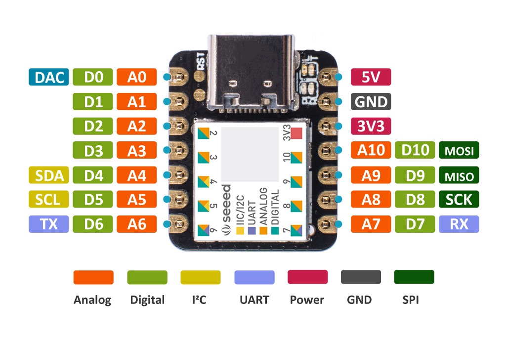
Seeeduino XIAO has 14 GPIO PINs, which can be used for 11 digital interfaces, 11 mock interfaces, 10 PWM interfaces (d1-d10), 1 DAC output pin D0, 1 SWD pad interface, 1 I2C interface, 1 SPI interface, 1 UART interface, Serial communication indicator (T/R), Blink light (L). The colors of LEDs(Power,L,RX,TX) are green, yellow, blue and blue. Moreover, Seeeduino XIAO has a Type-C interface which can supply power and download code. There are two reset pad, you can short connect them to reset the board.

Pinout:


Install Seeeduino XIAO board to Arduino IDE

With Arduino IDE installed, 
- select menu File > Preference, 
- add Additional Boards Manager URLs with: 
https://files.seeedstudio.com/arduino/package_seeeduino_boards_index.json

- Tools-> Board-> Boards Manager...
- Search "Seeeduino XIAO"
- Install "Seeed SAMD Boards"

Product page: Seeed Wiki - Seeeduino XIAO

Next: